
Laser distance measuring device

a laser generating device and laser technology, applied in distance measurement, instruments, surveying and navigation, etc., can solve the problems of ineffective improvement decrease of range capability and effective measurement distance of laser distance measuring device compared to indoor measurement capabilities, and increase of disturbing light in background, so as to improve the proportion of useful laser beam emitted from the laser generating device, improve the effect of signal to noise ratio and enhance the range capability of laser distance measuring device in a bright or strong light environmen

Inactive Publication Date: 2010-05-20
CHERVON HK LTD WANCHAI
View PDF3 Cites 32 Cited by
  • Summary
  • Abstract
  • Description
  • Claims
  • Application Information

AI Technical Summary

Benefits of technology

[0006]To overcome the problems explained above, the present invention provides a laser distance measuring device having a higher signal to noise ratio, specifically, a laser distance measuring device with an enhanced ranging capability under a bright or strong light environment.
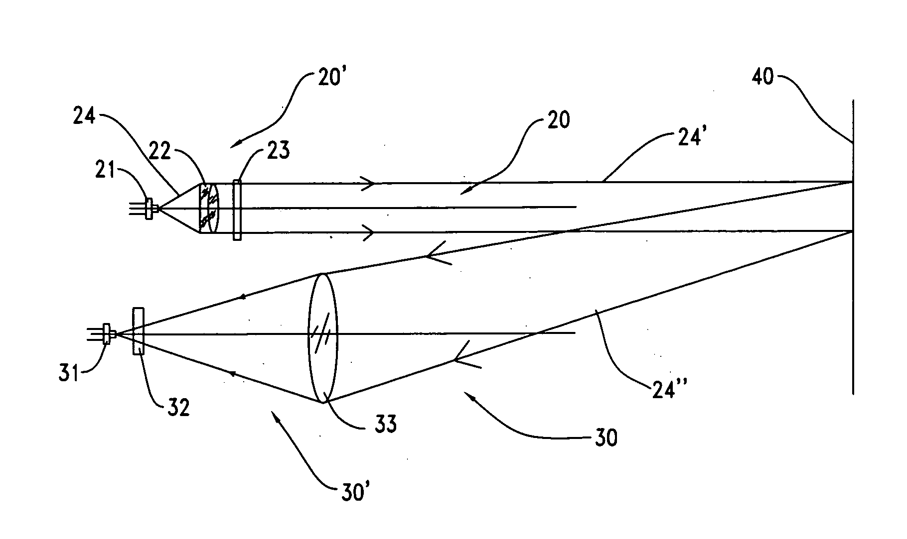
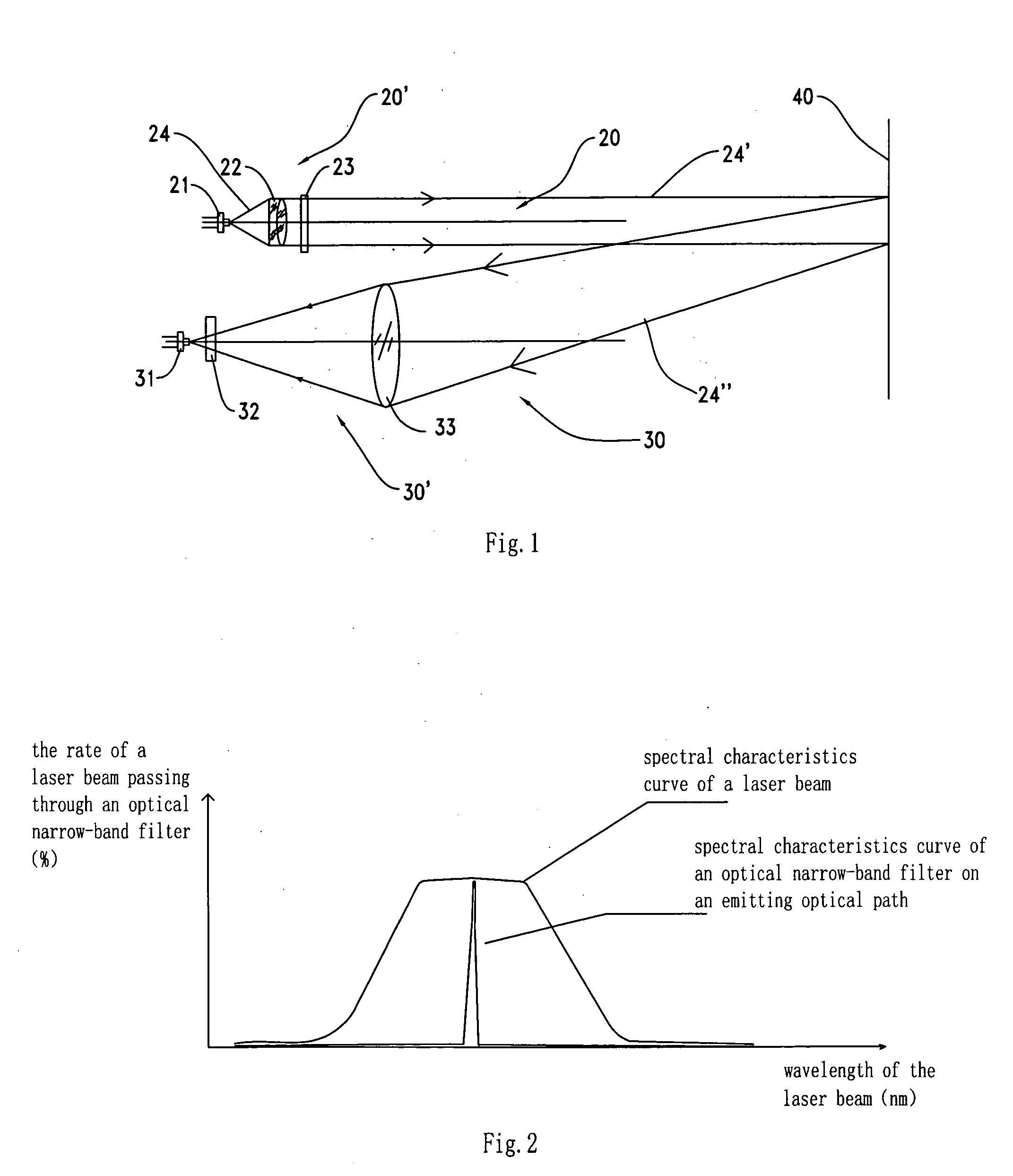
[0008]In the prior art, there is not an optical filter element arranged on the emitting optical path of the laser distance measuring device. Also, in the prior art, the effective power of the measuring beam is only a portion of the complete power of the laser beam emitted from the laser generating device. Therefore, in the prior art, the effective power of the measuring beam is significantly less than the upper limit of the maximum power allowed. Compared to the laser distance measuring device without an optical filter element on the emitting optical path, the laser distance measuring device disclosed in the present invention has an optical filter having a spectral bandwidth less than the spectral bandwidth of the laser beam. This allows the non-necessary portions of the laser beam emitted from the laser generating device to be filtered out by the optical filter. Therefore, the proportion of the useful measuring beam of the laser beam emitted from the laser generating device can be improved within the limits of the maximum emitting power allowed by safety regulations, and the power of the useful portions of the measuring beam emitted from the optical filter can be close to or equal to the upper limit of the maximum power allowed by safety regulations. As a result, the signal to noise ratio is improved and the ranging capability of the laser distance measuring device under a bright or strong light environment is enhanced.

Problems solved by technology

However, when used in an outdoor strong light environment, the intensity of the disturbing light in the background increases.
As a result, the disturbing light received by the photoreceiver increases and the signal to noise ratio (the ratio of the reflected measuring beam signals received by the photoreceiver to the disturbing light signals received by the photoreceiver) decreases, which results in both the ranging capability and effective measurement distance of the laser distance measuring device decreasing when compared to the indoor measurement capabilities.
As a result, when the useful portion of the measuring beam signal received by the photoreceiver is reduced along with the noise, the signal to noise ratio is not effectively improved.
Further, due to security concerns, there is a limit to the emitting power of the laser distance measuring device.
Accordingly, the ranging capability of the laser distance measuring device cannot be improved by arbitrarily increasing the emitting power of the emitter.

Method used


Image

  • Laser distance measuring device
  • Laser distance measuring device

Examples


Embodiment Construction

[0011]Referring to FIG. 1, a laser distance measuring device of a preferred embodiment of the present invention comprises an emitting part 20′ arranged on an emitting optical path 20 and a receiving part 30′ arranged on a receiving optical path 30. The emitting part 20′ includes a laser transmitter 21, a collimating lens group 22 and an optical narrow-band filter 23. The receiving part 30′ includes a photoelectric receiving and conversion device 31, an optical narrow-band filter 32 and a convergent lens 33. The laser transmitter 21 emits a laser beam 24. The laser beam 24 is collimated into a collimated laser beam by the collimating lens group 22. The collimated laser beam is then filtered using the optical narrow-band filter 23, and a measuring laser beam 24′ is produced and emitted from the laser distance measuring device. The measuring laser beam 24′ is reflected or scattered by an object 40 to be measured. A reflected laser beam 24″ is converged by the convergent lens 33 which i...


PUM


Abstract

The laser distance measuring device of the present invention comprises an emitting part having a laser generating device with a first spectral bandwidth arranged on an emitting optical path and a collimating lens. The emitting part also has an optical filter with a second spectral bandwidth which is less than the first spectral bandwidth. The laser distance measuring device also has a receiving part having a photoelectric receiving and conversion device to receive the measuring beam reflected by the object to be measured and convert it into an electric signal. Using the optical filter, most of the unneeded portions of the laser beam emitted from the laser are filtered out so that the useful proportion of the measuring beam of the laser beam is improved and the ranging capability of the laser distance measuring device under a bright or strong light environment is enhanced.

Description

CROSS-REFERENCE TO RELATED APPLICATIONS[0001]100011 This application claims priority under 35 U.S.C. §119 to CN 200820216153.X filed Nov. 17, 2008, which is hereby incorporated by reference.FEDERALLY SPONSORED RESEARCH OR DEVELOPMENT[0002]Not Applicable.TECHNICAL FIELD[0003]The present invention relates to a laser distance measuring device, and more particularly to a hand-held laser distance measuring device.BACKGROUND OF THE INVENTION[0004]Laser distance measuring devices have been widely used in construction, interior decoration and other fields due to their high accuracy of measurement. They have a measuring range up to tens of meters and are usually designed to be handheld devices. The general principles of measurement are as follows: an emitter emits an intensity modulated measuring beam to an object to be measured; the measuring beam is reflected or scattered by the object and is picked up by a photoreceiver and the distance from the object to be measured is determined based o...

Claims


Application Information

Patent Timeline
Patent Type & Authority Applications(United States)
IPC IPC(8): G01C3/08G01S17/32
CPCG01S17/32G01S7/4814G01S7/4811G01S17/08G01S17/36
Inventor YANG, DEZHONG
Owner CHERVON HK LTD WANCHAI
Learn More