
Implantable medical device and method for monitoring valve movements of a heart

Inactive Publication Date: 2010-05-13
ST JUDE MEDICAL
View PDF20 Cites 14 Cited by
  • Summary
  • Abstract
  • Description
  • Claims
  • Application Information

AI Technical Summary

Benefits of technology

[0012]A further object of the present invention is to provide a device and method that automatically obtains information that reflects the mechanical functioning and the pumping action of the heart in an accurate and reliable way.
[0016]Thus, the present invention is based on the insight of monitoring valve movements using electrodes placed adjacent to or substantially at the level of the valve plane of the heart by measuring impedance variations between at least one electrode placed adjacent to or substantially at the level of the valve plane and at least one electrode attached in an atrium and at least one electrode attached in a ventricle, respectively. The valve plane movements are caused by the pumping action of the heart, i.e. by the increased and decreased volume of the ventricles, and by studying the valve plane movements the contraction pattern and mechanical functioning of the heart can be monitored. The measured impedances can, in turn, be used to determine hemodynamic parameters reflecting the mechanical functioning of the heart. Thereby, it is possible to automatically obtain information that accurately and reliably reflects the mechanical functioning and the pumping action of the heart.

Problems solved by technology

If these conduction pathways do not function properly, a slight or severe delay in the propagation of electrical pulses may arise, causing asynchronous contraction of the ventricles which would greatly diminish the pumping efficiency of the heart.
Patients who exhibit pathology of these conduction pathways, such as patients with bundle branch blocks, etc., can thus suffer from compromised pumping performance.
Some medical conditions, however, affect the relationship between the electrical and mechanical activity of the heart and, therefore, measurements of the electrical activity only cannot be relied upon as indicative of the true status of the heart or as suitable for triggering stimulation of the heart.

Method used


Image

  • Implantable medical device and method for monitoring valve movements of a heart
  • Implantable medical device and method for monitoring valve movements of a heart
  • Implantable medical device and method for monitoring valve movements of a heart

Examples


Embodiment Construction

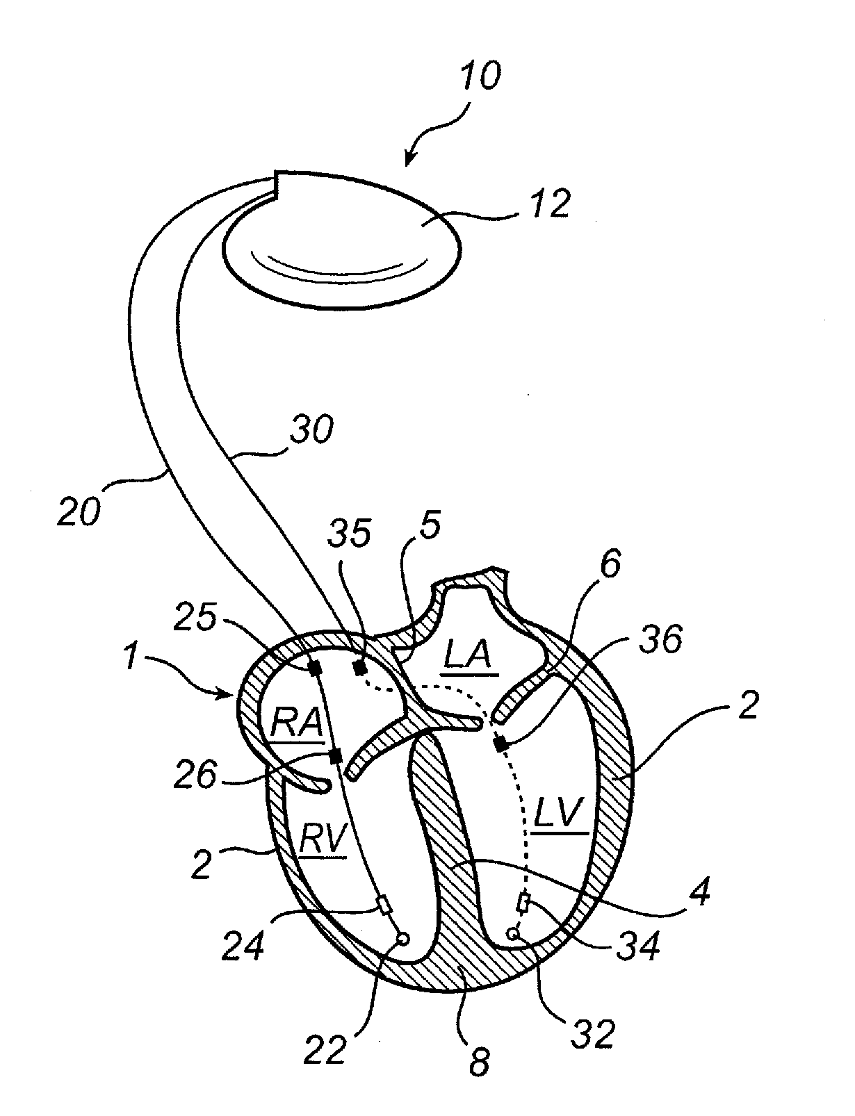
[0044]The following is a description of exemplifying embodiments in accordance with the present invention. This description is not to be taken in limiting sense, but is made merely for the purposes of describing the general principles of the invention. Thus, even though particular types of implantable medical devices such as heart stimulators will be described, e.g. biventricular pacemakers, the invention is also applicable to other types of cardiac stimulators such as dual chamber stimulators, implantable cardioverter defibrillators (ICDs), etc.

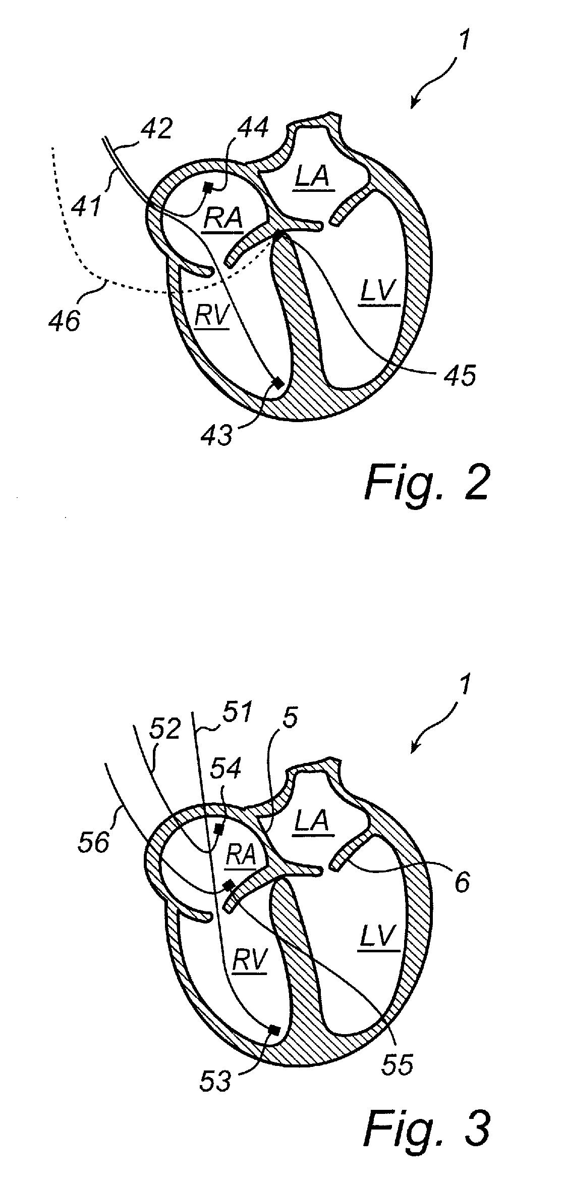
[0045]In the following a number of different electrode configurations suitable for obtaining impedances reflecting the mechanical functioning of the heart, and in particular movements of the valve plane, will be discussed.

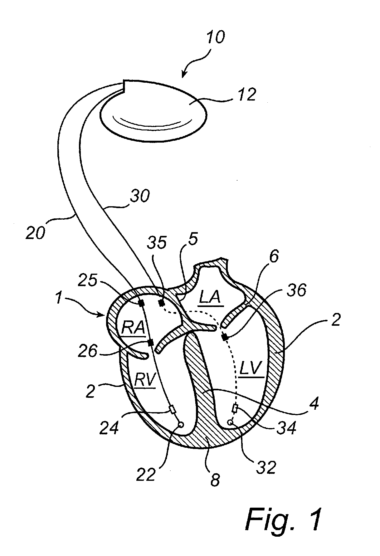
[0046]With reference first to FIG. 1, there is shown a implantable medical device according to an embodiment of the present invention. According to this embodiment, the invention is implemented in a stimulation device 10. T...


PUM


Abstract

An implantable medical device for monitoring the movements of the valve planes of the heart to determine at least one hemodynamic measure reflecting a mechanical functioning of a heart of a patient, includes an impedance measuring circuit that measures impedance between at least electrode pairs including at least one electrode placed substantially at the level of the valve plane. The measured impedances reflect valve plane movements. A hemodynamic parameter determining circuit determines at least one hemodynamic parameter based on the impedances reflecting the mechanical functioning of the heart.

Description

BACKGROUND OF THE INVENTION[0001]1. Field of the Invention[0002]The present invention generally relates to the field of implantable heart stimulation devices, such as pacemakers, implantable cardioverter-defibrillators (ICD), and similar cardiac stimulation devices that also are capable of monitoring and detecting electrical activities and events within the heart. More specifically, the present invention relates to an implantable medical device for monitoring the movements of the valve planes of the heart to determine at least one hemodynamic measure reflecting a mechanical functioning of a heart of a patient.[0003]2. Description of the Prior Art[0004]Implantable heart stimulators that provide stimulation pulses to selected locations in the heart, e.g. selected chambers, have been developed for the treatment of cardiac diseases and dysfunctions. Heart stimulators have also been developed that affect the manner and degree to which the heart chambers contract during a cardiac cycle in...

Claims


Application Information

Patent Timeline
IPC IPC(8): A61N1/368
CPCA61N1/36521A61N1/3682A61N1/36578
Inventor BJORLING, ANDERSTUVSTEDT, CECILIANILSSON, KENTHNOREN, KJELL
Owner ST JUDE MEDICAL
Learn More