
Color sequence offset modulation method and device

a color sequence and offset modulation technology, applied in the direction of instruments, static indicating devices, etc., can solve the problem that the light transmission curve b>2/b> cannot fully reflect the timing signal, and achieve the effect of avoiding color deviation and preventing color differences

Inactive Publication Date: 2010-05-13
POWERTIP TECH
View PDF2 Cites 7 Cited by
  • Summary
  • Abstract
  • Description
  • Claims
  • Application Information

AI Technical Summary

Benefits of technology

[0004]The primary objective of the present invention is to provide an offset modulation method and device to eliminate color difference and retain the purity of colors, whereby the problem of color deviation is solved.
[0010]Therefore, the present invention can prevent from the color difference caused by color mixing during the close delay interval. In a case of needing pure colors, the present invention can avoid the color deviation caused by color mixing. In a case of needing mixed colors, the present invention can present the designed colors correctly.

Problems solved by technology

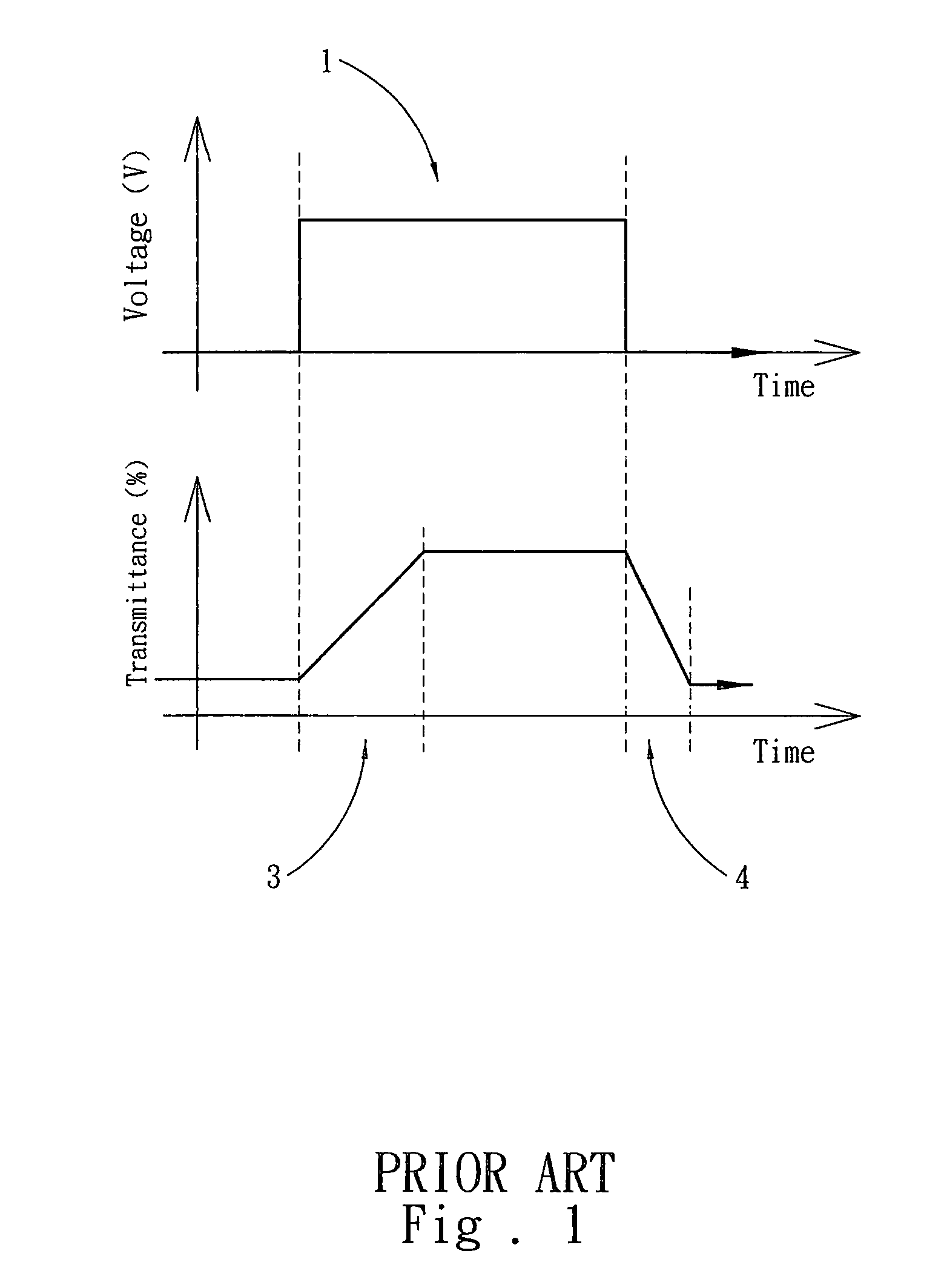
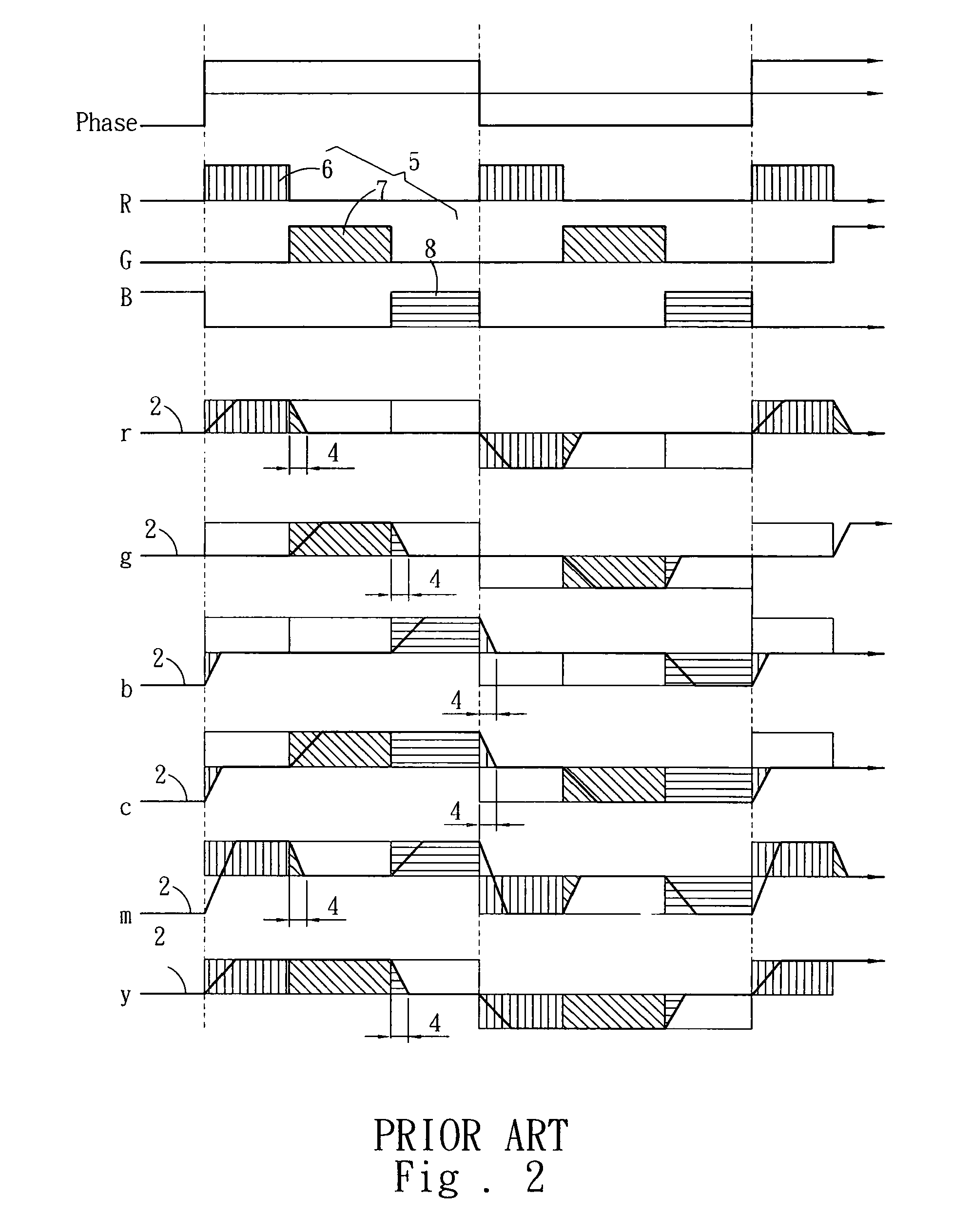
However, the light transmission curve 2 cannot fully reflect the timing signal 1 because the delayed response of liquid crystal molecules.

Method used


Image

  • Color sequence offset modulation method and device
  • Color sequence offset modulation method and device
  • Color sequence offset modulation method and device

Examples


first embodiment

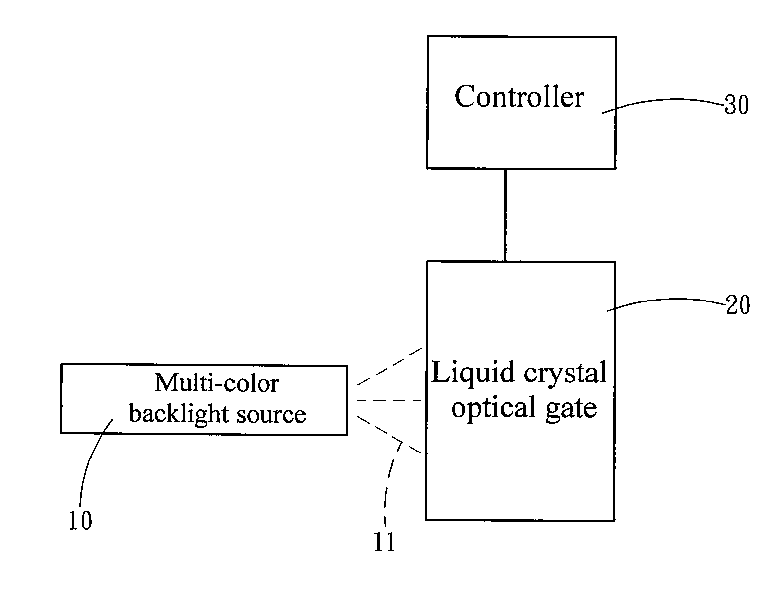
[0017]Refer to FIG. 3 and FIG. 4. In a first embodiment, the device of the present invention comprises a multi-color backlight source 10, a liquid crystal optical gate 20 and a controller 30. The multi-color backlight source 10 is arranged near the liquid crystal optical gate 20, and the controller 30 is electrically coupled to the liquid crystal optical gate 20.

[0018]The multi-color backlight source 10 emits at least two colored backlights 11 with a dark interval 12 therebetween. The colored backlights 11 include a red backlight 111, a green backlight 112 and a blue backlight 113. The colored backlight 11 may have the dark interval 12 at the instant that the multi-color backlight source 10 begins to emit the colored backlight 11.

[0019]The colored backlights 11 are projected onto the liquid crystal optical gate 20. The liquid crystal optical gate 20 has a light blocking state and a light permeable state. The controller 30 generates a timing signal 31. The timing signal 31 may be an ...

second embodiment

[0021]Refer to FIG. 5. In a second embodiment, the time point of switching two opposite phases of the timing signal 31 is identical to the time point of sequentially shifting the colored backlights 11. In such a mode, the three colored backlights 11 have almost identical light flux loss in the open delay interval 211 and close delay interval 212. Thus, no matter whether the present invention generates pure-color lights or mixed-color lights, the ratio of the component lights is almost identical to the ratio of the original design. Therefore, the present invention can present the designed colors correctly.

[0022]As described above, when generating pure-color lights the present invention can prevent the active colored backlight from mixing with another colored backlight 11 and avoids color deviation. When generating mixed-color lights, the present invention can present the designed colors correctly.


PUM


Abstract

The present invention discloses a color sequence offset modulation method and device, which modulates the colored backlights of a multi-color backlight source to have a dark interval in the time points of shifting the colored backlights and makes the dark interval coincide with the close delay interval caused by the delayed response of liquid crystal, whereby the latter colored backlight will not mix with the former colored backlight during the close delay interval, wherefore the present invention can avoid the color deviation caused by color mixing and can present the designed colors correctly.

Description

FIELD OF THE INVENTION[0001]The present invention relates to a display method and device of a color liquid crystal display, particularly to a color sequence offset modulation method and device, which can prevent from color mixing-induced color deviation and present the designed colors correctly.BACKGROUND OF THE INVENTION[0002]In FSC LCD (Field Sequential Color Liquid Crystal Display), multi-color backlights are sequentially emitted and pass through optical liquid crystal gates. FSC LCD opens and closes the liquid crystal optical gates to sequentially generate pure-color fields, and then the visual persistence of human eyes mixes the pure colors to present various colors. Refer to FIG. 1. The timing signal 1 is used to open and close the liquid crystal optical gates. However, the light transmission curve 2 cannot fully reflect the timing signal 1 because the delayed response of liquid crystal molecules. Thus, there are open delays 3 and close delays 4 appearing in the light transmis...

Claims


Application Information

Patent Timeline
Patent Type & Authority Applications(United States)
IPC IPC(8): G09G3/36
CPCG09G3/3413G09G2320/0242G09G2310/0235
Inventor CHEN, CHIA-HUIHUANG, CHIU-YUANCHIEN, CHUN-TSAI
Owner POWERTIP TECH
Learn More