
Doctor blade system for print unit intended for a photogravure printing machine

a technology of photogravure printing machine and blade system, which is applied in the direction of printing press, printing press, rotary intaglio printing press, etc., can solve the problems of limiting the movement of the doctor blade support, the drawback of having a pivoting point, and the inability of the blade to optimally follow the surfa

Active Publication Date: 2010-05-13
BOBST MEX SA
View PDF10 Cites 0 Cited by
  • Summary
  • Abstract
  • Description
  • Claims
  • Application Information

AI Technical Summary

Benefits of technology

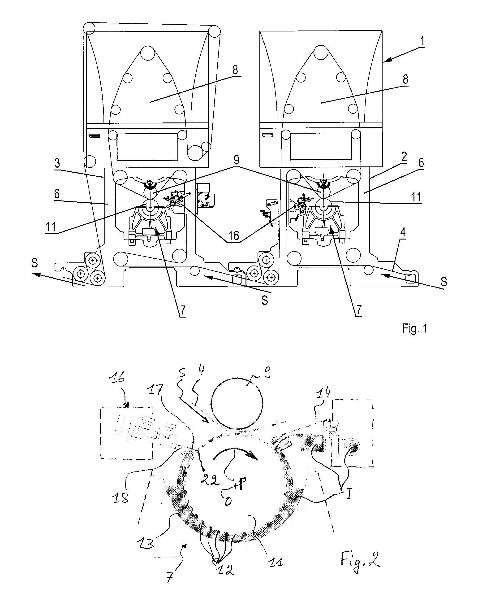
[0026]One main problem that the invention proposes to address consists in developing a doctor blade system allowing optimal scraping of a peripheral surface of the cylinder. A second problem is to produce a doctor blade system allowing both a reciprocating motion of the blade and optimum cylinder scraping effectiveness using this same blade. A third problem is how to provide a doctor blade system permanently installed in a print unit, while ensuring that it is exactly adapted to each new cylinder. A fourth problem is to use a doctor blade system that is independent of the print carriage and therefore of the cylinder, with a number of options for adjusting the doctor blade system relative to the cylinder. A fifth problem is to obtain a doctor blade system for a print unit, which is both simple and inexpensive to produce. Yet another problem is fitting a doctor blade system in a print unit for photogravure printing machine that makes it possible to obtain a high print quality.
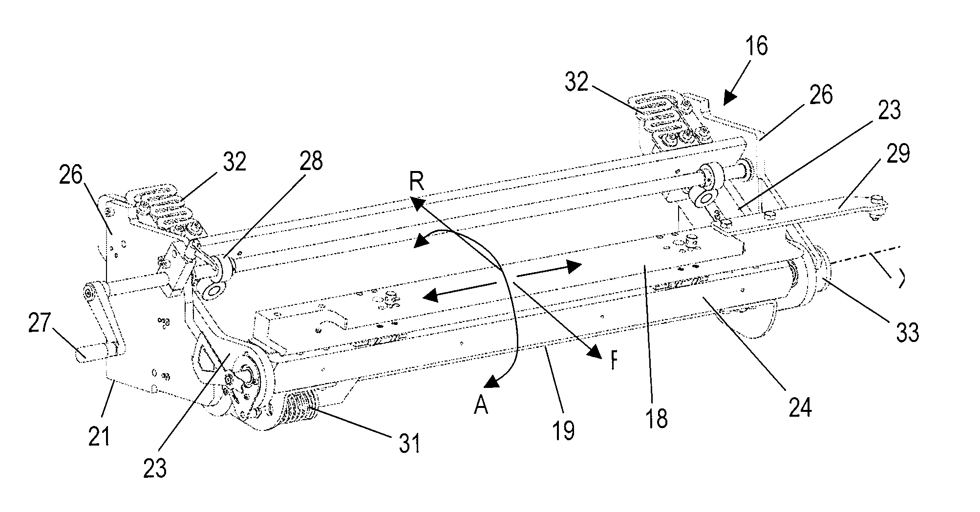
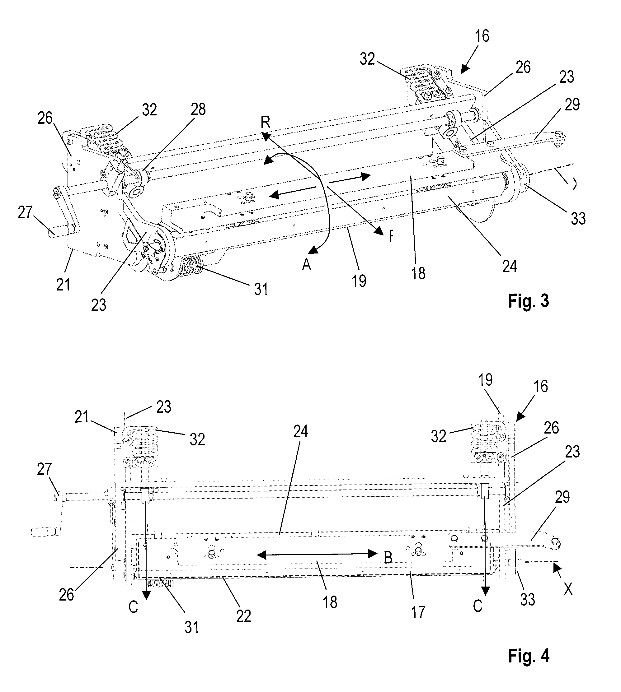
[0038]The reciprocating means are used to avoid excessively fast localized wear of the blade, adversely affecting the print quality. The doctor blade system thus combines for the blade an ability to be moved freely, until the latter comes into and remains constantly in contact with the surface of the cylinder, and a capacity to perform forward and backward movement on this surface of this cylinder. Furthermore, the means for providing reciprocating motion of the blade move only the doctor blade support and its blade, thus reducing the weight of the parts in rapid motion.
[0040]Favorably, the system can comprise means for compensating a torque created by the reciprocating motion of the blade. The torque is created by the additional degree of freedom conferred on the supporting hub, on the doctor blade support and on the blade, associated with the reciprocating motion of the doctor blade support and of the blade. The means for compensating the torque can comprise a washer, fitted at one end of a rotation axis of the supporting hub. This rotation axis makes it possible to adjust an angle between the blade and the peripheral surface of the engraved cylinder and constitutes an attachment point between the supporting hub and the structure.
[0041]The means for providing a reciprocating motion of the blade can comprise a push arm projecting from the doctor blade support. This finger can come into contact with push means for the reciprocating motion, which are motorized, and independent of the doctor blade system. The means for providing a reciprocating motion of the blade can comprise a return spring, positioned between the doctor blade support and the supporting hub, and ensuring a free return of the doctor blade support, after it has been pushed.

Problems solved by technology

However, such a device presents the drawback of having a pivoting point, which is reflected in the existence of an abutment point for the blade, when it is moved in the direction of the surface to be scraped.
The blade will not be able to optimally follow the surface to be scraped.
Furthermore, the elongate openings limit the movements of the doctor blade support.
Furthermore, the presence of the journals for the pivoting means that the thrust of the pistons against the doctor blade support produces undesirable rotational movements.

Method used


Image

  • Doctor blade system for print unit intended for a photogravure printing machine
  • Doctor blade system for print unit intended for a photogravure printing machine
  • Doctor blade system for print unit intended for a photogravure printing machine

Examples


Embodiment Construction

[0026]One main problem that the invention proposes to address consists in developing a doctor blade system allowing optimal scraping of a peripheral surface of the cylinder. A second problem is to produce a doctor blade system allowing both a reciprocating motion of the blade and optimum cylinder scraping effectiveness using this same blade. A third problem is how to provide a doctor blade system permanently installed in a print unit, while ensuring that it is exactly adapted to each new cylinder. A fourth problem is to use a doctor blade system that is independent of the print carriage and therefore of the cylinder, with a number of options for adjusting the doctor blade system relative to the cylinder. A fifth problem is to obtain a doctor blade system for a print unit, which is both simple and inexpensive to produce. Yet another problem is fitting a doctor blade system in a print unit for photogravure printing machine that makes it possible to obtain a high print quality.

[0027]Th...


PUM


Abstract

A doctor blade system intended for a print unit includes a doctor blade support provided with a blade, an edge of the blade is able to come into contact with a peripheral surface of an engraved printing cylinder, a supporting hub, on which the doctor blade support is mounted, a structure fixing the supporting hub to a frame of the print unit. Apparatus provides a reciprocating motion of the blade along the peripheral surface of the engraved cylinder roughly parallel to the axis of revolution of the engraved cylinder. Thrust elements drive movement of the blade along the direction of the peripheral surface of the engraved cylinder. The reciprocating apparatus directly drives the doctor blade support. The thrust element or elements move the supporting hub and the doctor blade support and the blade to maintain a constant contact over the entire length of the edge of the blade with the peripheral surface of the engraved cylinder.

Description

CROSS REFERENCE TO RELATED APPLICATION[0001]The present application is a 35 U.S.C. §§371 national phase conversion of PCT / EP2008 / 002441, filed Mar. 28, 2008, which claims priority of European Application No. 07008586.5, filed Apr. 27, 2007, incorporated by reference herein. The PCT International Application was published in the French language.BACKGROUND OF THE INVENTION[0002]The present invention relates to a doctor blade system, provided with a doctor blade. The invention also relates to a print unit equipped with a doctor blade system. The invention finally relates to a photogravure printing machine, incorporating at least one print unit.[0003]Photogravure is a rotary printing method that can be used for numerous media, including paper or cardboard, using engraved cylinders. Photogravure printing is used in particular for high quality publication with large print runs where the graphics have to play an important role in the promotion of a product, such as a package in the form of...

Claims


Application Information

Patent Timeline
Patent Type & Authority Applications(United States)
IPC IPC(8): B41F9/10
CPCB41F9/1009
Inventor ROBADEY, PIERRE
Owner BOBST MEX SA
Learn More