Eureka AIR delivers breakthrough ideas for toughest innovation challenges, trusted by R&D personnel around the world.

Multi-planar taper lock screw with increased rod friction

a taper lock screw and multi-planar technology, applied in the field of multi-planar taper lock screw with increased rod friction, can solve the problems of increasing the difficulty of spinal rod securement, and many conventional devices for locking a spinal rod to a hook or screw do not offer the flexibility to allow the spinal rod

Active Publication Date: 2010-05-06
K2M
View PDF28 Cites 117 Cited by
  • Summary
  • Abstract
  • Description
  • Claims
  • Application Information

AI Technical Summary

Benefits of technology

[0014]One step includes locking the one or more flat surfaces of the spinal rod with the one or more locking features of the saddle of the collet of the first spinal fixation device. The method includes the step of locking the spinal rod to the second spinal fixation device where the second spinal fixation device includes a collet having a saddle defining one or more locking features engagable with the one or more flat surfaces of the spinal rod.

Problems solved by technology

Many conventional devices for locking a spinal rod to a hook or screw do not offer the needed flexibility to allow the spinal rod to be easily connected to misaligned adjacent vertebrae.
In addition, the spinal rod may excessively rotate and / or axially translate when being positioned within the screw, making the spinal rod securement even more difficult.
Some effort has been made to provide a multi-planar screw; however, even for devices that have attempted to address the issue of securing spinal rods to misaligned vertebrae, there remains the problem of providing such a multi-planar screw and spinal rod combination that can be easily locked and unlocked in position without the need to exert additional torque to the device or force on the patient.

Method used


Image

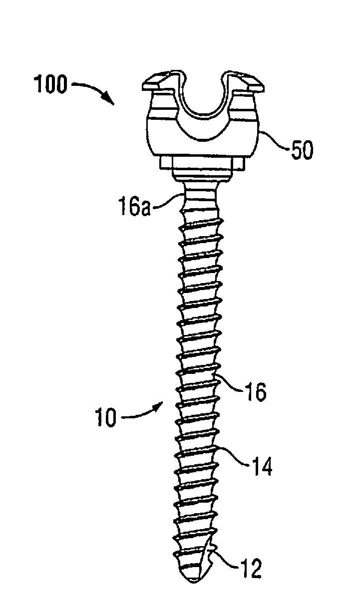
  • Multi-planar taper lock screw with increased rod friction
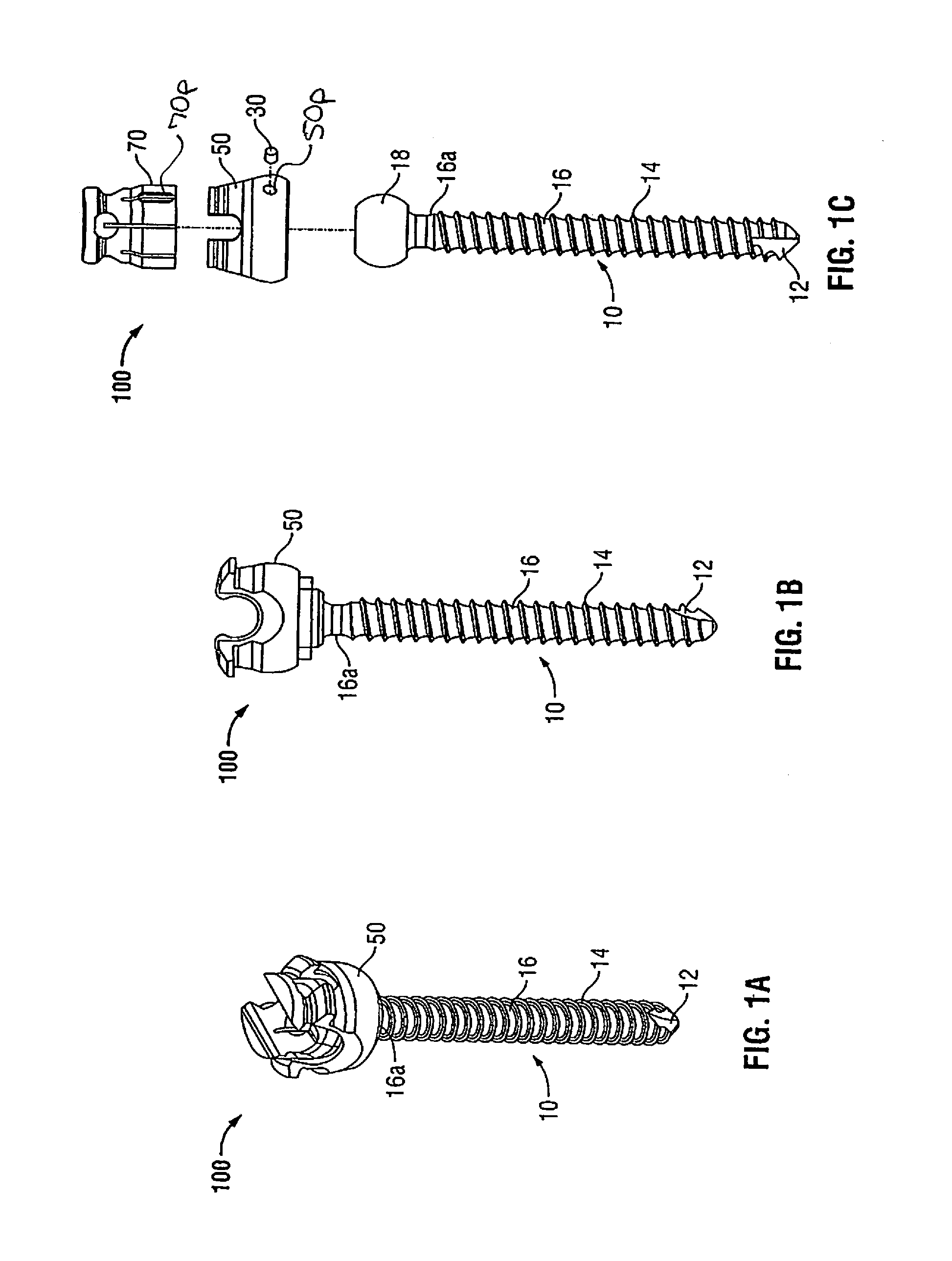
  • Multi-planar taper lock screw with increased rod friction
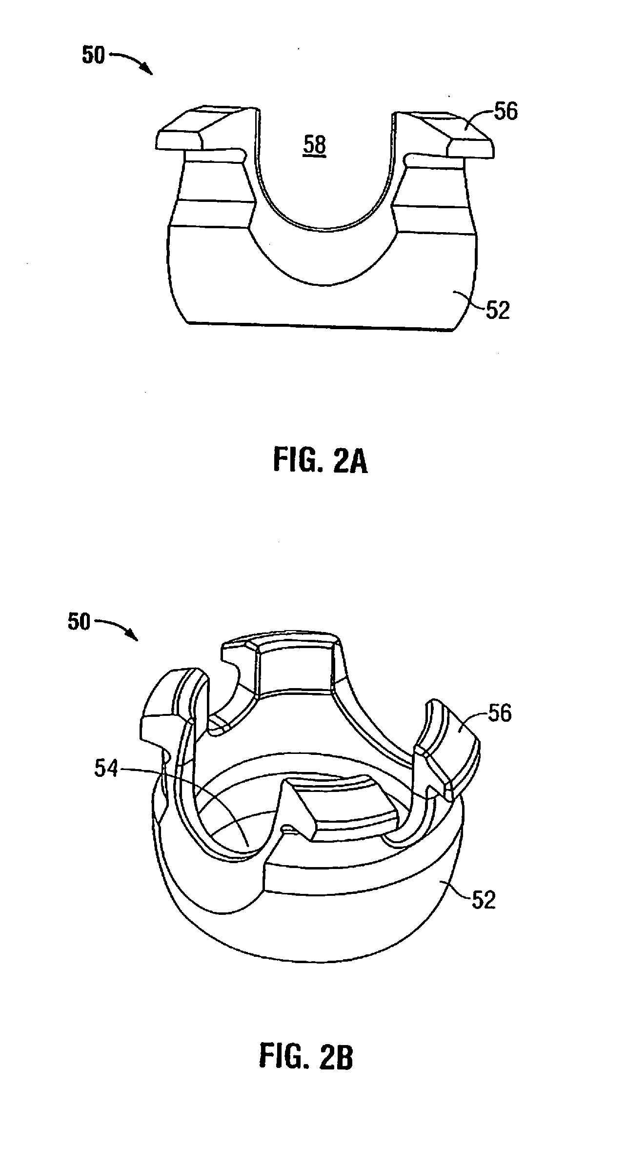
  • Multi-planar taper lock screw with increased rod friction

Examples


Embodiment Construction

[0046]Various embodiments of the presently disclosed spinal fixation device will now be described in detail with reference to the drawings, wherein like reference numerals identify similar or identical elements. In the drawings and in the description that follows, the term “proximal,” will refer to the end of the device that is closest to the operator, while the term “distal” will refer to the end of the device that is farthest from the operator. In addition, the term “cephalad” is used in this application to indicate a direction toward a patient's head, whereas the term “caudad” indicates a direction toward the patient's feet. Further still, for the purposes of this application, the term “medial” indicates a direction toward the middle of the body of the patient, whilst the term “lateral” indicates a direction toward a side of the body of the patient (i.e., away from the middle of the body of the patient). The term “posterior” indicates a direction toward the patient's back, and th...


PUM


Abstract

A spinal fixation device includes a coupling, a pedicle screw, and a collet. The coupling has an opening extending therethrough. The pedicle screw has a head mounted to a shank that is positionable within a first vertebral body. The collet is receivable in the opening of the coupling and engagable with the head of the pedicle screw. The collet is selectively positionable between a first position and a second position where the collet engages a spinal rod and prevents one or both of axial and rotational movement of the spinal rod. The collet is adapted to facilitate the connection of the spinal rod to a second vertebral body. The collet defines a saddle having one or more locking features for engaging the spinal rod.

Description

CROSS-REFERENCE TO RELATED APPLICATIONS[0001]This application claims priority to, and the benefit of, U.S. Provisional Patent Application Ser. No. 61 / 198,385, filed Nov. 5, 2008, the contents of which are hereby incorporated by reference in their entirety.BACKGROUND[0002]1. Technical Field[0003]The present disclosure relates generally to orthopedic surgery and in particular to devices and prosthesis for stabilizing and fixing the bones and joints of the body.[0004]2. Background of Related Art[0005]It is a common surgical procedure to stabilize and fix bones and bone fragments in a particular spatial relationship with fixation devices to correct the location of skeletal components due to injury or disease. This can be accomplished by using a number of fixation devices such as bone pins, anchors, or screws placed in bone across a discontinuity (e.g., a fracture) in the bone, bone fragments, adjacent vertebrae, or joints. These fixation devices can be connected by a rod to maintain a d...

Claims


Application Information

Patent Timeline
Patent Type & Authority Applications(United States)
IPC IPC(8): A61B17/70A61B17/86A61B17/88
CPCA61B17/701A61B17/7037
Inventor BARRUS, MICHAELHAMBURGER, MARY P.
Owner K2M
Why Eureka
Eureka Blog
Learn More