Frequency Hopping Scheme for OFDMA System

a frequency hopping and frequency technology, applied in the field of communication systems, can solve problems such as the inability to straightforwardly apply a technique to a system

Inactive Publication Date: 2010-05-06
TELEFON AB LM ERICSSON (PUBL)
View PDF1 Cites 12 Cited by
  • Summary
  • Abstract
  • Description
  • Claims
  • Application Information

AI Technical Summary

Benefits of technology

[0006]According to a first aspect of the present invention, there is...

Problems solved by technology

However, this type of technique cannot be straightforwardly applied to a system in which variable bandwidths, and hence variable numbers of sub-channel...

Method used


Image

  • Frequency Hopping Scheme for OFDMA System
  • Frequency Hopping Scheme for OFDMA System
  • Frequency Hopping Scheme for OFDMA System

Examples


Embodiment Construction

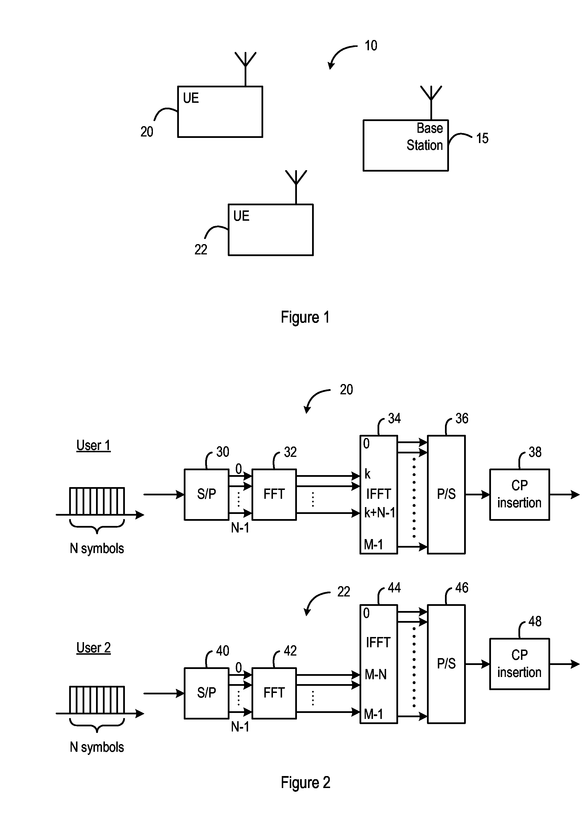
[0017]FIG. 1 illustrates a part of a communication system 10, in which a base station 15 is in wireless communication with first and second user equipments (UEs) 20, 22 respectively.

[0018]It will be apparent to the person skilled in the art that the illustrated part of the communication system 10 may form part of a cellular wireless communication system, in which multiple base stations provide coverage to mobile user equipments within a network coverage area.

[0019]FIG. 2 illustrates the operation of one part of the communication system 10, in accordance with an embodiment of the present invention. Specifically, FIG. 2 illustrates parts of the first and second user equipments (UEs) 20, 22 respectively.

[0020]Within the first user equipment (UE) 20, data is generated in a conventional manner for transmission over a wireless communications link to the base station 15. In this illustrated case, N symbols of data are generated within one time period. The data is passed to a serial-paralle...


PUM


Abstract

Available bandwidth is divided into multiple sub-channels, and respective sub-bands containing one or more of these sub-channels are allocated to one or more users. A first frequency allocation is determined, and mathematical operators are used to determine at least one further frequency allocation from the first frequency allocation. A frequency hopping sequence is then determined, including the first frequency allocation, and the or each further frequency allocation. A network node may perform the allocation method, and a user equipment may operate using the allocated bandwidth.

Description

BACKGROUND OF THE INVENTION[0001]This invention relates to a communication system, and in particular to an orthogonal frequency division multiple access (OFDMA) communication system, in which each user has a frequency hopping scheme.[0002]In an OFDMA system, the available frequency bandwidth is divided into a number of sub-channels, and these sub-channels can be allocated to different users of the system.[0003]The document 3GPP 25.814 “Physical Layer Aspects for Evolved UTRA” v1.2.0 section 9.2.1, describes an uplink access scheme, in which each user can be allocated a variable bandwidth, formed from a number of contiguous sub-channels.[0004]It is known that allowing frequency hopping is a way to improve the reliability of a communication system. That is, when a user is transmitting on one frequency at any given time, there is defined a sequence of frequency channels, and the user transmits on the channels of the defined sequence in turn.[0005]However, this type of technique cannot ...

Claims


Application Information

Patent Timeline
IPC IPC(8): H04J13/06H04L27/26H04B1/713H04W72/04
CPCH04B1/7143H04L5/0007H04L5/0037H04L5/0064H04L27/2601H04B1/713
Inventor ALMGREN, MAGNUSNYBERG, HENRIKSKILLERMARK, PER
Owner TELEFON AB LM ERICSSON (PUBL)
Why Eureka
Try Eureka