
Adjustable Monotube Shock Absorber

a shock absorber and monotube technology, applied in the direction of shock absorbers, mechanical equipment, transportation and packaging, etc., can solve the problems of high cost, high complexity and high cost of systems, and the need for a relatively expensive hollow piston rod to adjust the shock absorber

Inactive Publication Date: 2010-05-06
FURRER FREDRICK J
View PDF27 Cites 107 Cited by
  • Summary
  • Abstract
  • Description
  • Claims
  • Application Information

AI Technical Summary

Benefits of technology

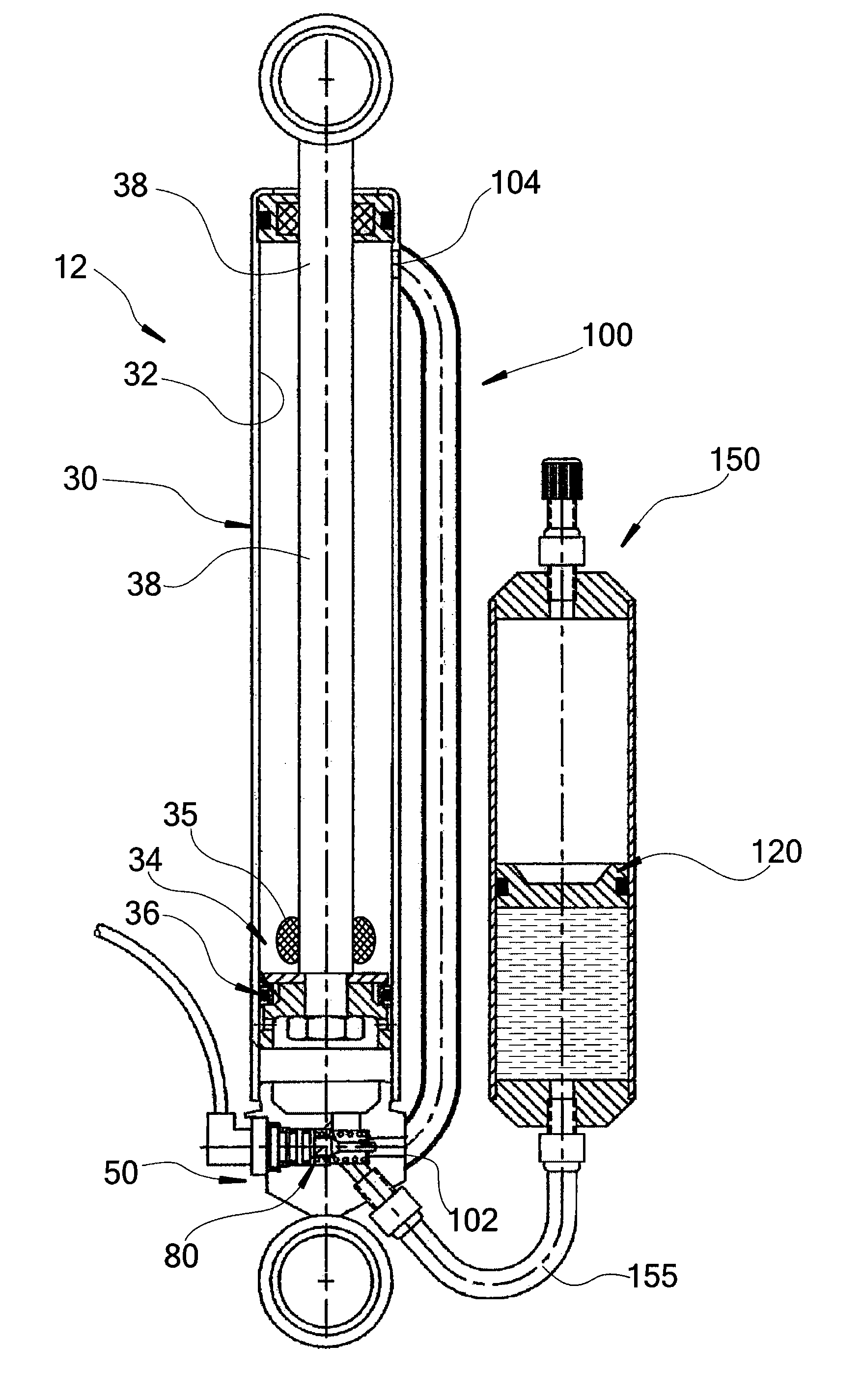
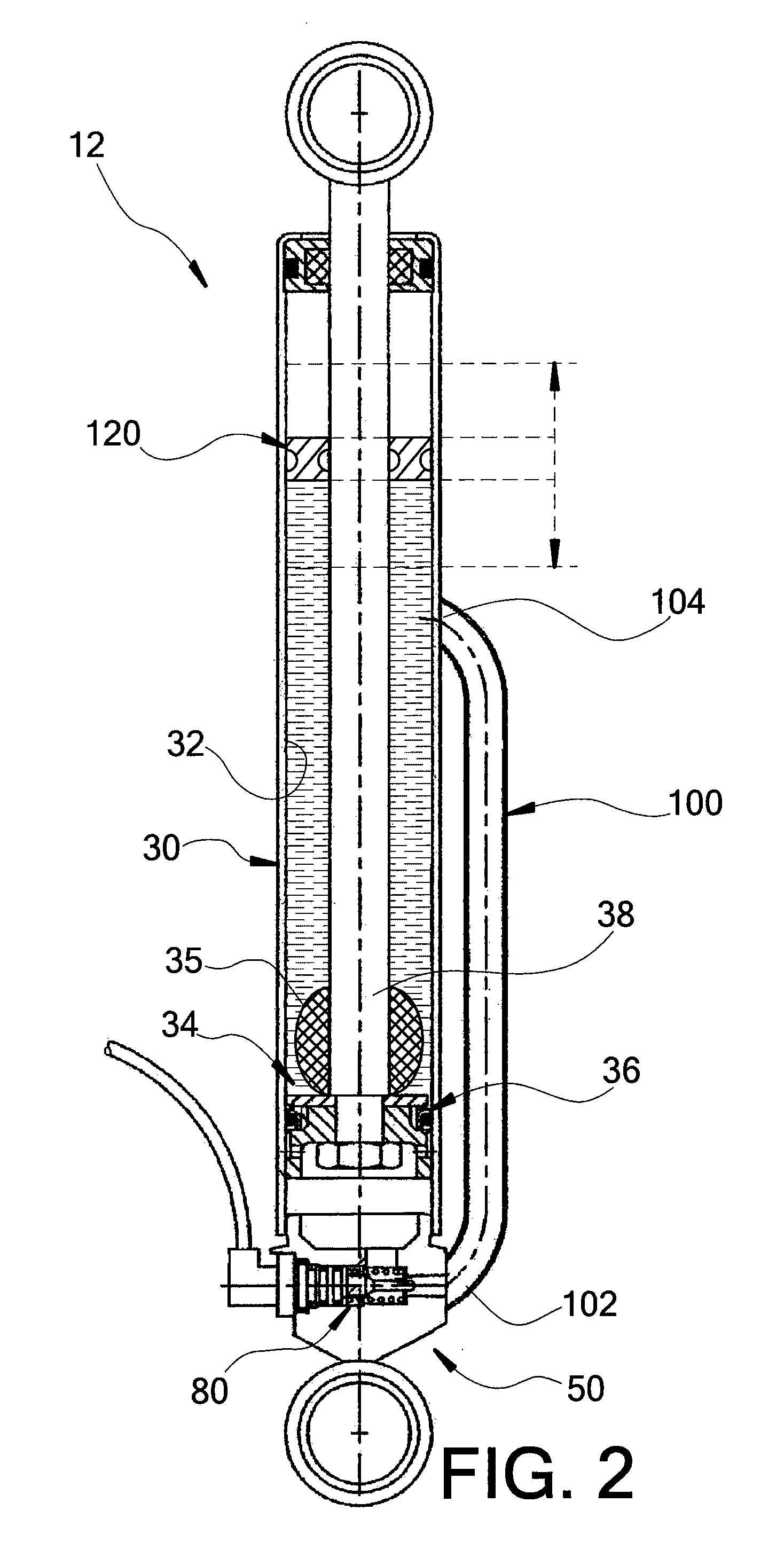
"The present invention is a monotube shock absorber that can be controlled remotely and can be incorporated into a system that controls multiple monotube shock absorbers in a motor vehicle. The shock absorber includes a body tube with a cylindrical sidewall, a rod, a floating piston, and a working piston. An external bypass tube is positioned outside of the cylindrical sidewall and includes a lower end fluidly connected to the lower oil cavity and an upper end fluidly connected to the upper oil cavity. A control valve assembly is provided between the lower bypass tube end and the lower oil cavity portion to control the oil flow and damping characteristics of the shock absorber. The present invention also includes a remotely controlled monotube shock absorber system with a user interface and a controller for managing performance characteristics of multiple adjustable monotube shock absorbers."

Problems solved by technology

In many cases, such adjustable shock absorbers suffer from the need for a relatively expensive hollow piston rod.
Furthermore, multi-tube shock absorbers typically house relatively less oil therein and correspondingly have relatively diminished heat dissipation capability when compared to monotube shock absorbers.
Such systems are highly complex and expensive.
Furthermore, hollow piston rods can be expensive to produce and are relatively more proven to impact type and other damage, as compared to solid rod configurations, which can compromise the use-life of such designs.
These zoning adjustable systems are typically complex, are incapable of remote adjustability, and are expensive, whereby their most common implementations are within racing and motorsports applications.

Method used


Image

  • Adjustable Monotube Shock Absorber
  • Adjustable Monotube Shock Absorber
  • Adjustable Monotube Shock Absorber

Examples


Embodiment Construction

[0027]The present invention and the various features and advantageous details thereof are explained more fully with reference to the non-limiting embodiments described in detail in the following description.

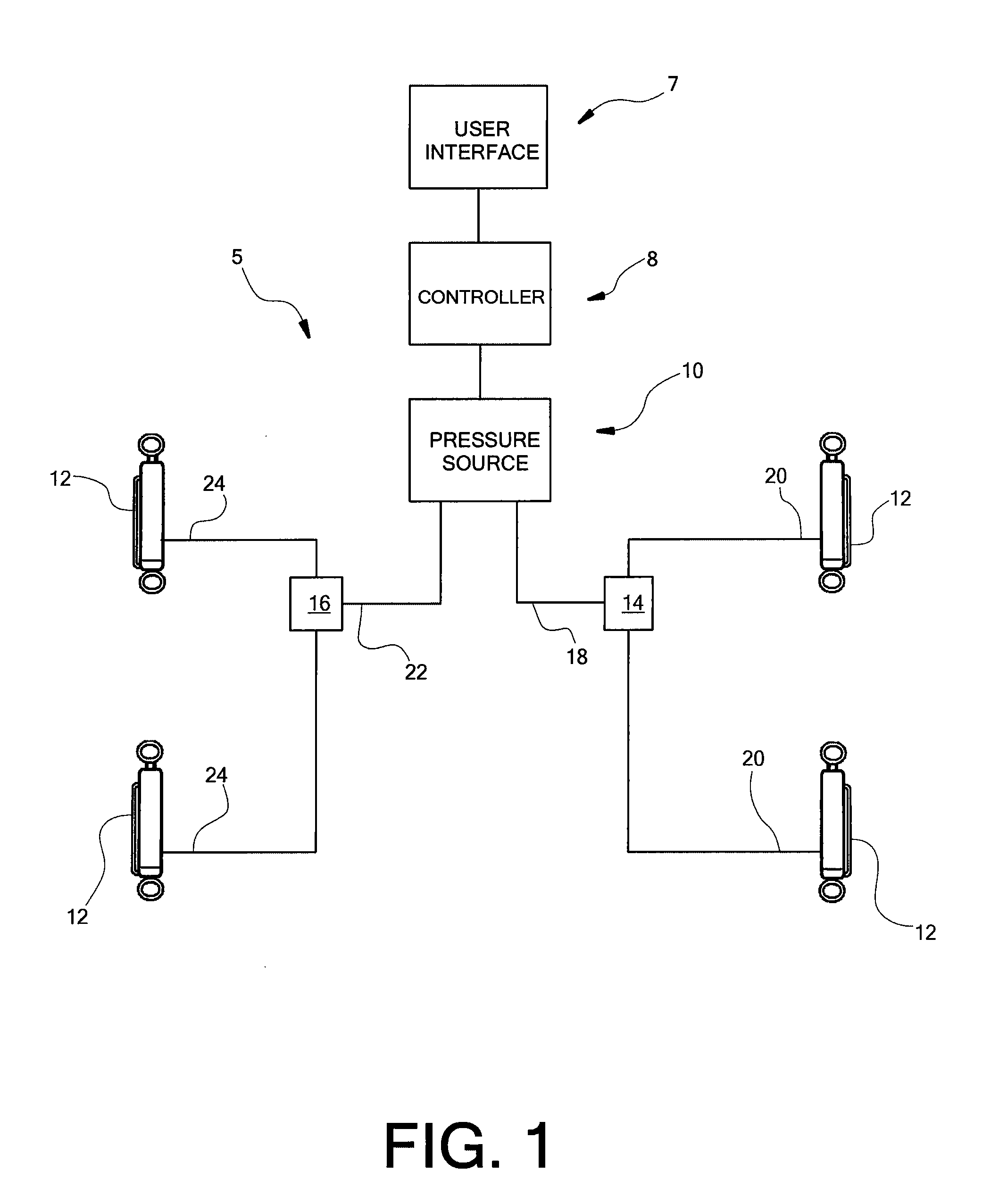
[0028]Turning now to the drawings, FIG. 1 shows a system 5 that incorporates multiple adjustable monotube shock absorbers, e.g., monotube shock absorbers 12, a user interface 7, a controller 8, and a fluid pressure source 10. Typically, the multiple monotube shock absorbers 12 are arranged as, e.g., two shock absorbers 12 mounted to the front suspension elements of a vehicle, and two shock absorbers 12 mounted to the rear suspension elements of the vehicle. The user interface 7 can be mounted on the center console of the vehicle, so as to be accessible by the driver for manual adjustment, or elsewhere in the passenger compartment that allows suitable accessibility by the user. Alternatively, the user interface 7 can be integrated into the electronic controls of the vehicle, where...


PUM


Abstract

A monotube shock absorber that can be adjusted remotely or otherwise, and a corresponding system are provided. The monotube shock absorber includes a body tube that houses a working piston therein and a bypass tube that is attached to but external with respect to the body tube. A control valve influences flow volume and rate of oil that passes through the bypass tube in a manner that correspondingly influences damping and / or other characteristics of the monotube shock absorber. The monotube shock absorber can include a floating piston separating a volume of gas from a volume of oil. The volumes of gas and oil may be entirely housed in the body tube or may be at least partially housed in an external reservoir that can include an anti-cavitation valve.

Description

CROSS-REFERENCE TO RELATED APPLICATIONS[0001]This application claims the benefit of and priority to U.S. Provisional Patent Application Ser. No. 61 / 111,888, filed on Nov. 6, 2008, the entirety of which is expressly incorporated by reference herein.BACKGROUND OF THE INVENTION[0002]1. Field of the Invention[0003]This invention relates to remotely adjustable shock absorbers and, more particularly, to remotely adjustable monotube shock absorbers and systems incorporating the same.[0004]2. Discussion of the Related Art[0005]Remotely adjustable shock absorbers continue to grow in popularity. Numerous previous attempts have been made to provide such adjustable shock absorbers. Knecht, U.S. Pat. No. 4,650,042, Ashiba, U.S. Pat. No. 4,519,186, and Emura, U.S. Pat. No. 4,620,619, all disclose shock absorbers which utilize electrically powered actuators in the shock absorber to modify damping characteristics. Similarly, Ellis, U.S. Pat. No. 4,122,923, and Schupner, U.S. Pat. No. 4,164,274, dis...

Claims


Application Information

Patent Timeline
Patent Type & Authority Applications(United States)
IPC IPC(8): B60G17/033F16F9/06
CPCB60G17/08B60G2202/24B60G2206/41B60G2500/104F16F9/061F16F9/466
Inventor FURRER, FREDRICK J.
Owner FURRER FREDRICK J
Learn More