
Weld parameter interface

a parameter interface and interface technology, applied in the field of welding, can solve the problems of inconvenient procedures for operators, reducing the overall efficiency of manufacturing processes, and wasting years of operator experience, and achieve the effect of increasing simplicity

Active Publication Date: 2010-05-06
ILLINOIS TOOL WORKS INC
View PDF24 Cites 91 Cited by
  • Summary
  • Abstract
  • Description
  • Claims
  • Application Information

AI Technical Summary

Benefits of technology

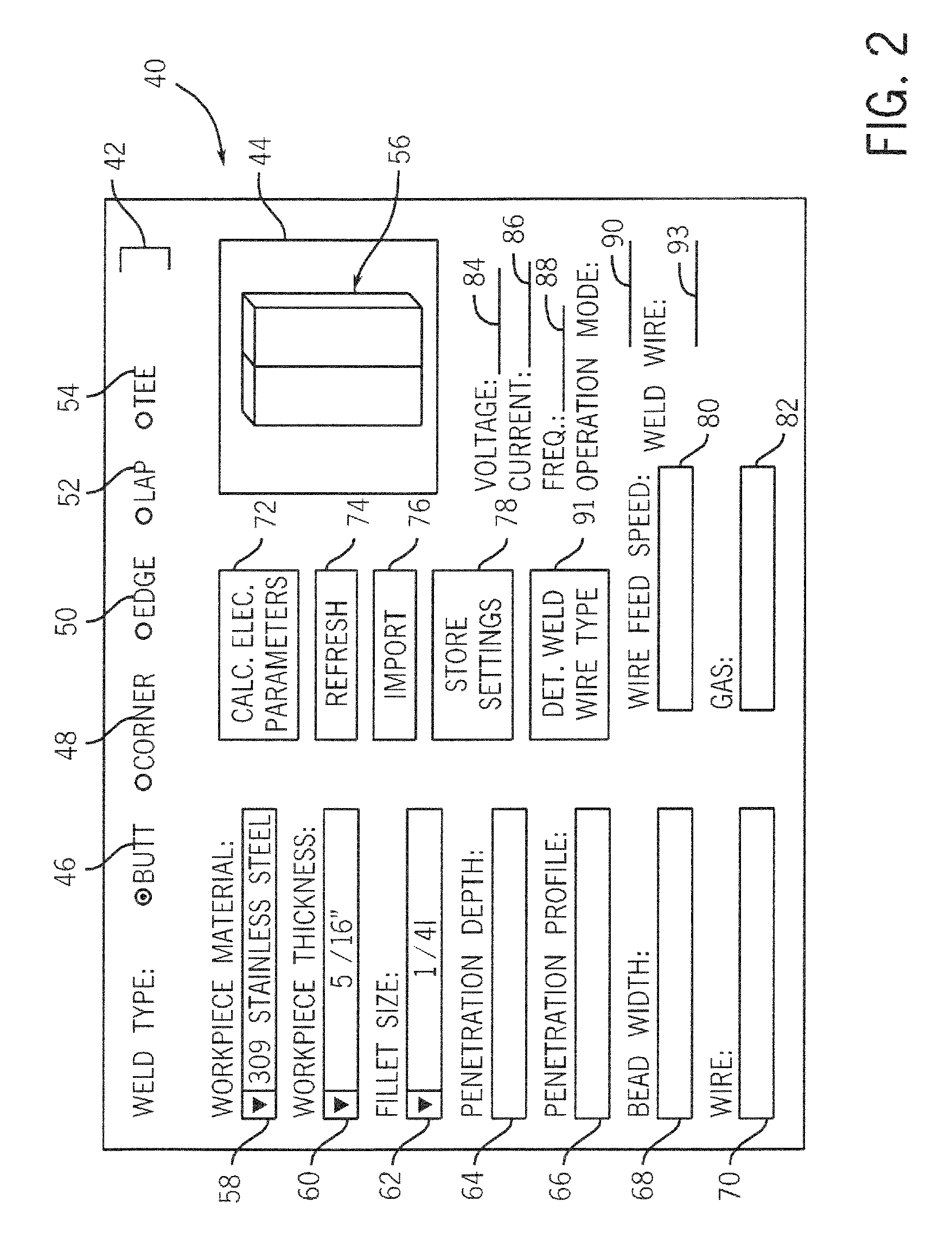
[0007]The present invention provides a system and method for adjusting power source parameters which overcomes the aforementioned drawbacks. Embodiments of the present invention provide for adjustment / control of power source settings based on descriptions of a weld procedure to be performed. In addition, embodiments of the present invention include interfaces which are integrated into remote devices and present simple weld-term options, for increased simplicity.

Problems solved by technology

In contrast, many weld operators are prone to understand welding processes in terms of the physical characteristics of the weld itself.
When an operator must spend significant amounts of time in being constantly re-trained in new electrical settings or when an operator takes longer to adjust a new power source, the overall efficiency of a manufacturing process is reduced.
Additionally, when experienced operators must be re-trained to think of weld settings in terms of electrical parameters, years of operator experience may be put to waste.
These procedures may be inconvenient for an operator who is welding remotely from the power source.
When an operator is located inside a ship hull, for example, walking back to a power source located outside the ship hull can present a very real inconvenience.

Method used


Image

  • Weld parameter interface
  • Weld parameter interface
  • Weld parameter interface

Examples


Embodiment Construction

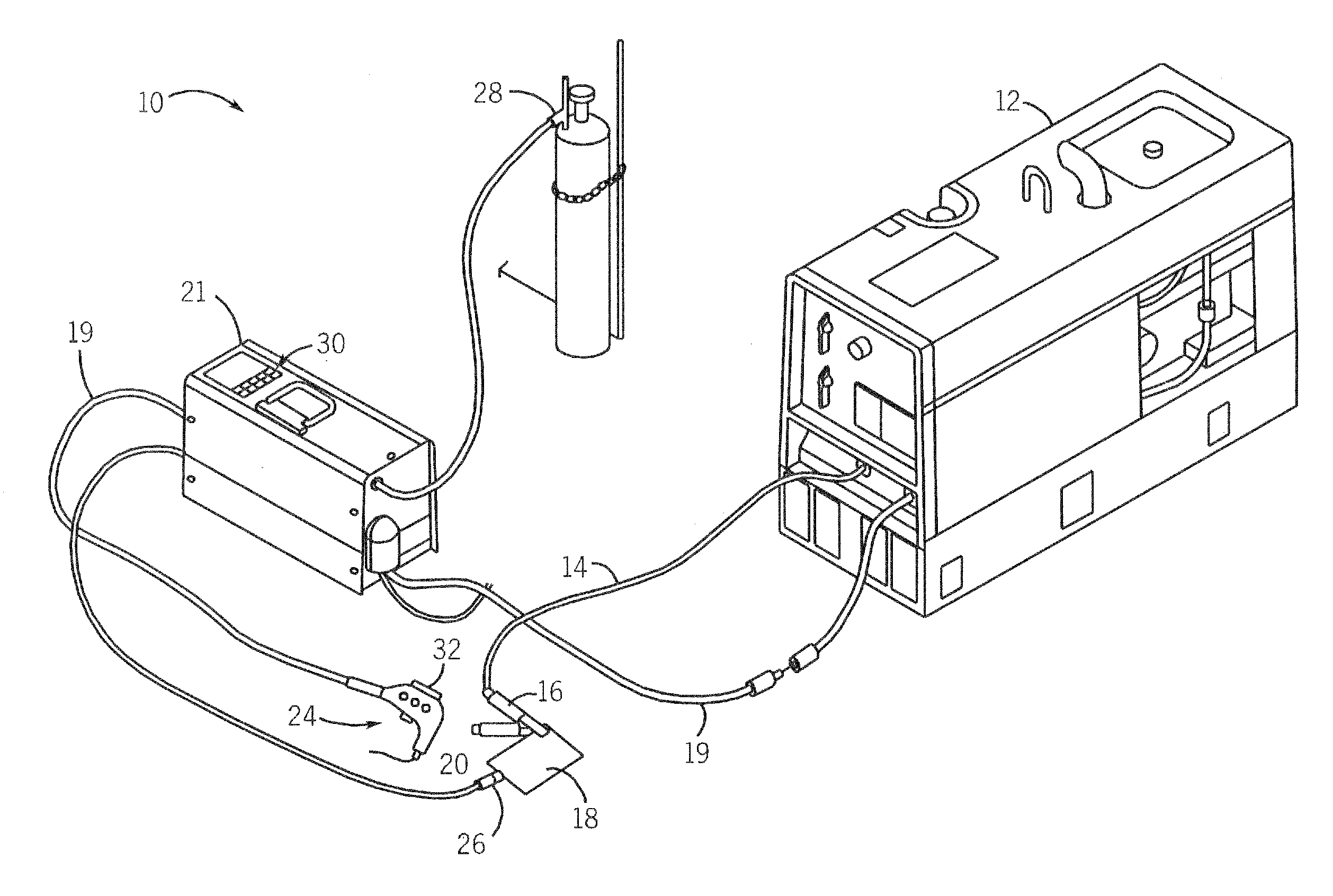
[0019]The present invention finds applicability with all welding or weld-related systems including, but not limited to, systems utilizing power sources which are located remotely from the operator and the workpiece / weld. Therefore, embodiments of the invention will be discussed below with respect to systems which utilize wire feeders, weld robots, sophisticated torches, other user-adapted accessories, and the like. However, it is to be understood that the features and advantages described for a given welding-type system or configuration are equally applicable to other welding-type systems. For example, discussion of the present invention with respect to remote wire feeders shall be understood to extend to other remote devices equivalently.

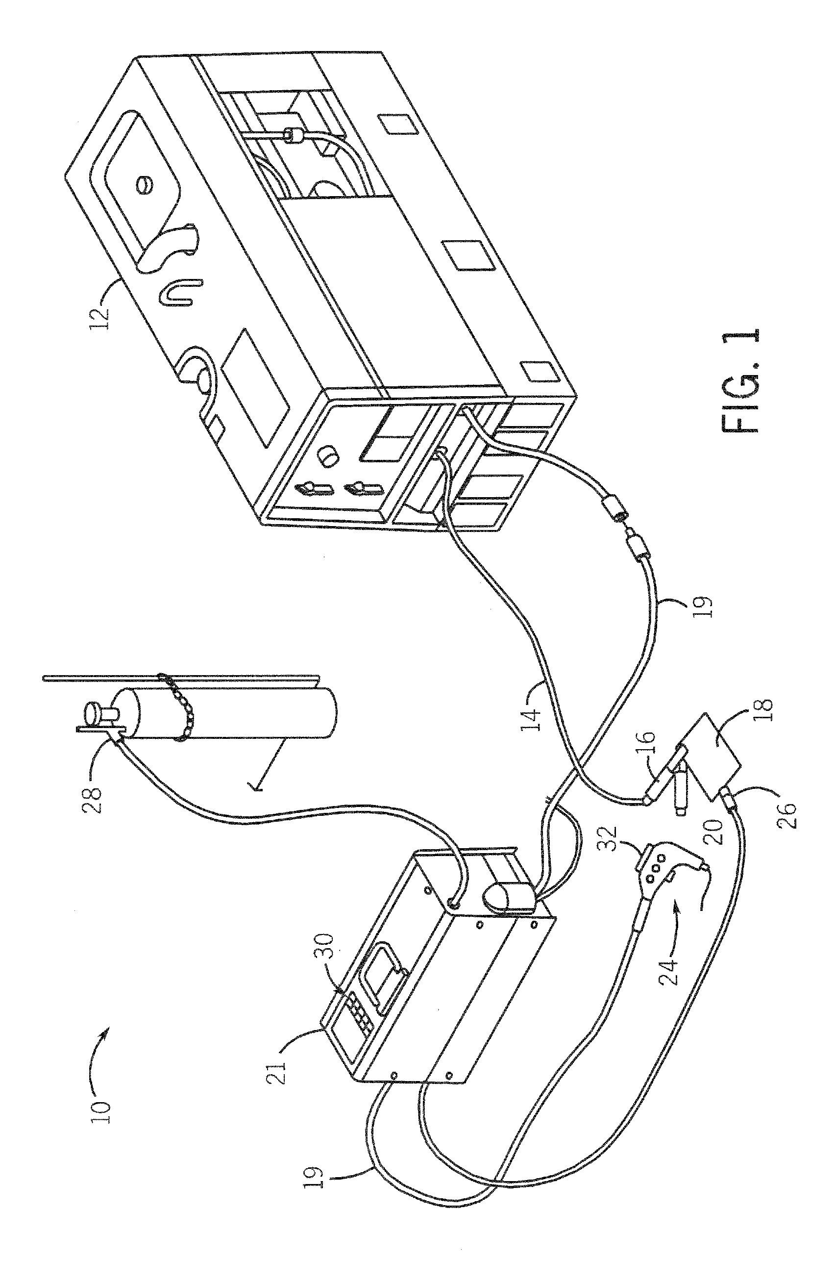
[0020]Referring to FIG. 1, a welding-type system 10 is shown incorporating the present invention. System 10 includes at least one power source 12, which can be an AC or a DC welding power supply operable in either a constant current (CC) or a const...


PUM

PropertyMeasurementUnit
poweraaaaaaaaaa
power source parametersaaaaaaaaaa
electrical parametersaaaaaaaaaa

Abstract

A system and method for determining settings or parameters for a welding-type power source are provided. By presenting an operator with an interface that is positioned along the path of a weld cable and configured to input weld characteristics, an operator is not required to determine electrical parameters for setting a welding-type power source output at the power source. The interface is presented to the operator at a remote welding-type device, such as a wire feeder, a weld robot, a torch, or the like. From the operator-specified weld characteristics, the system and method determine appropriate settings for the power source. In some embodiments, the system and method may automatically set the power source accordingly.

Description

BACKGROUND OF THE INVENTION[0001]The present invention relates generally to welding, and, more particularly, to a weld parameter interface system and method which calculate electrical requirements or other settings for a welding process from weld characteristics, such as a material to be welded, joint configuration, weld dimensions or other parameters. By allowing users to describe a weld to be performed rather than electrical requirements, the system and method of the present invention can simplify and / or automate the electrical calibration of a power source for a particular welding procedure.[0002]As new advances in the welding arts develop, the level of user knowledge required to operate advanced welders has correspondingly increased. In other words, the more features and capabilities incorporated into a welder, the more an operator must learn or remember in order to utilize the new features and capabilities. Many present welding systems and power sources prompt a user to specify...

Claims


Application Information

Patent Timeline
Patent Type & Authority Applications(United States)
IPC IPC(8): B23K9/10
CPCB23K9/0953B23K9/1087B23K9/1062
Inventor ULRICH, JAMES F.ALBRECHT, BRUCEHOLVERSON, TODD E.
Owner ILLINOIS TOOL WORKS INC
Learn More