
Fast Data Recovery From HDD Failure

a data recovery and fast technology, applied in the field of data recovery in storage systems, can solve the problems of long time data recovery also having the possibility of encountering the next disk failure, slow data recovery approach, long time performance decline, etc., and achieve the effect of fast data recovery and fast rebuilding

Active Publication Date: 2010-04-29
HITACHI LTD
View PDF11 Cites 47 Cited by
  • Summary
  • Abstract
  • Description
  • Claims
  • Application Information

AI Technical Summary

Benefits of technology

[0004]Embodiments of the invention provide methods and apparatus for fast data recovery from storage device failure such as HDD failure. Employing data distribution in plural disks, RAID in distributed data, page mapping management between virtual volume and physical disks, and parallel access data recovery by copying from pages to pages, the invention achieves fast rebuild, capacity efficiency, and self-recovery.

Problems solved by technology

As a result, the RAID approach is slow to rebuild from disk failure and will be slower each year.
Long time data rebuild has the possibility of causing long time performance decrement by corrosion between rebuilt disk I / O and normal disk I / O.
Long time data rebuild also has the possibility of encountering the next disk failure during data recovery.
When node failure occurs, the storage system copies the data to another node(s) from redundant data.

Method used


Image

  • Fast Data Recovery From HDD Failure
  • Fast Data Recovery From HDD Failure
  • Fast Data Recovery From HDD Failure

Examples


first embodiment

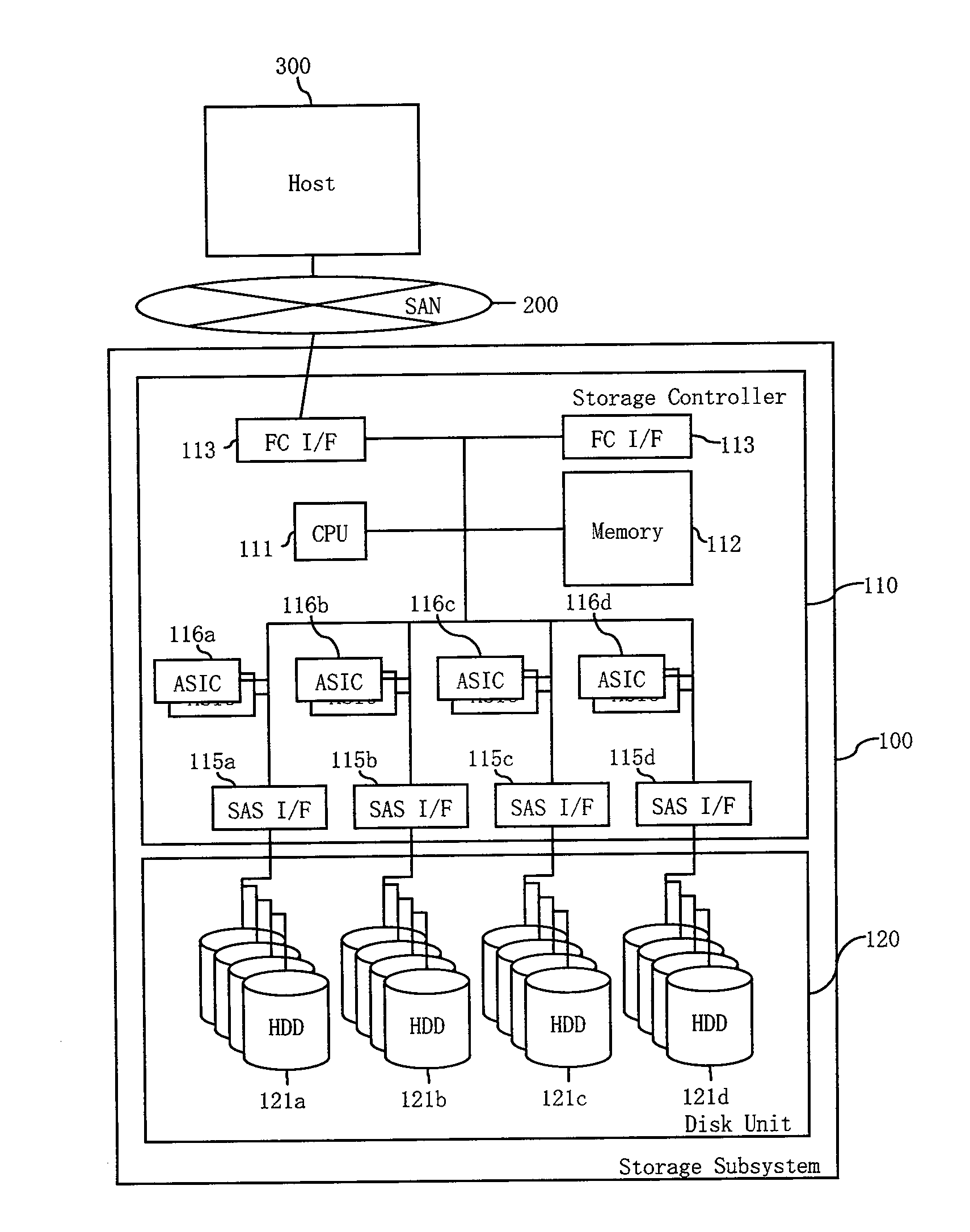
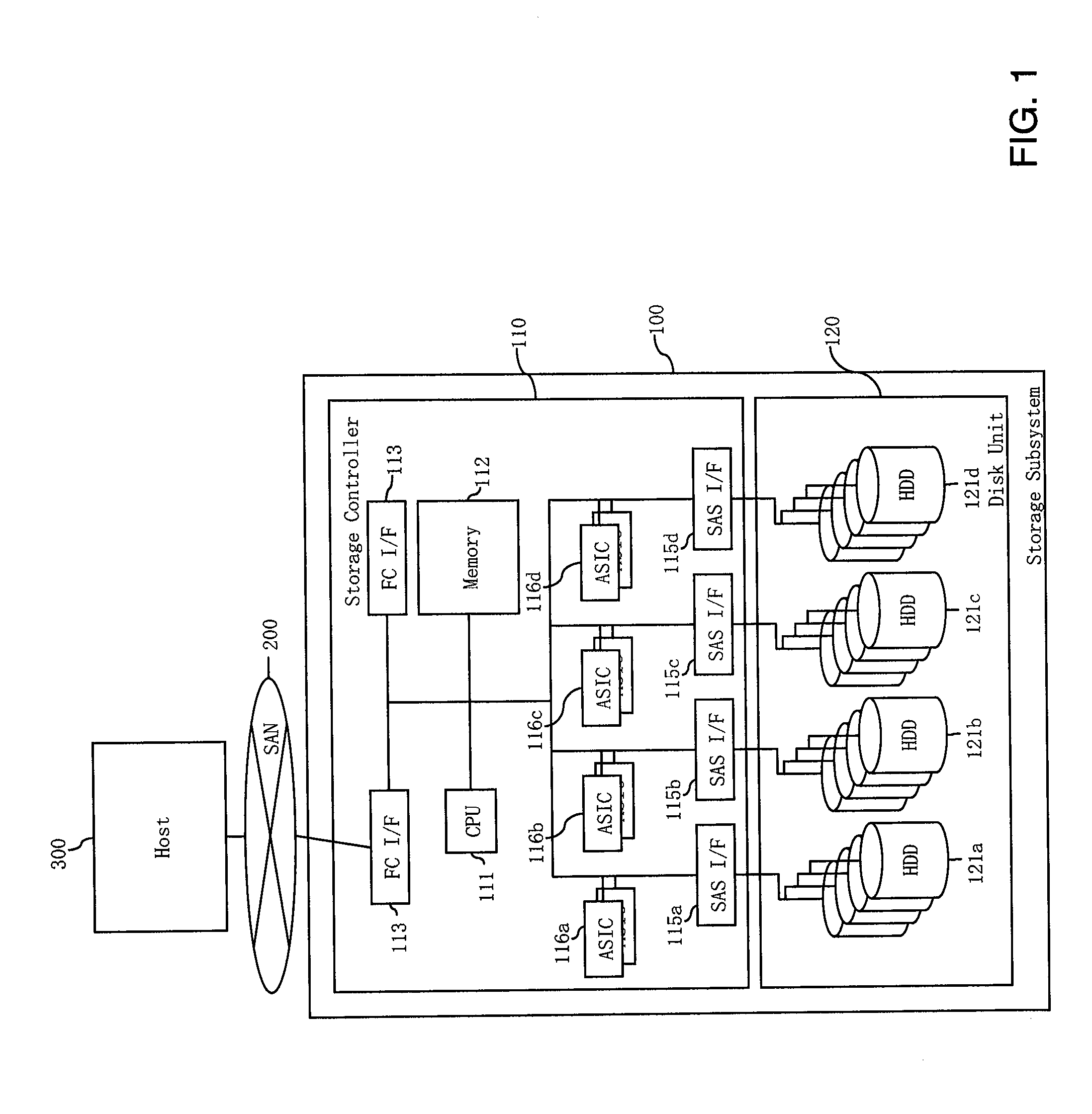
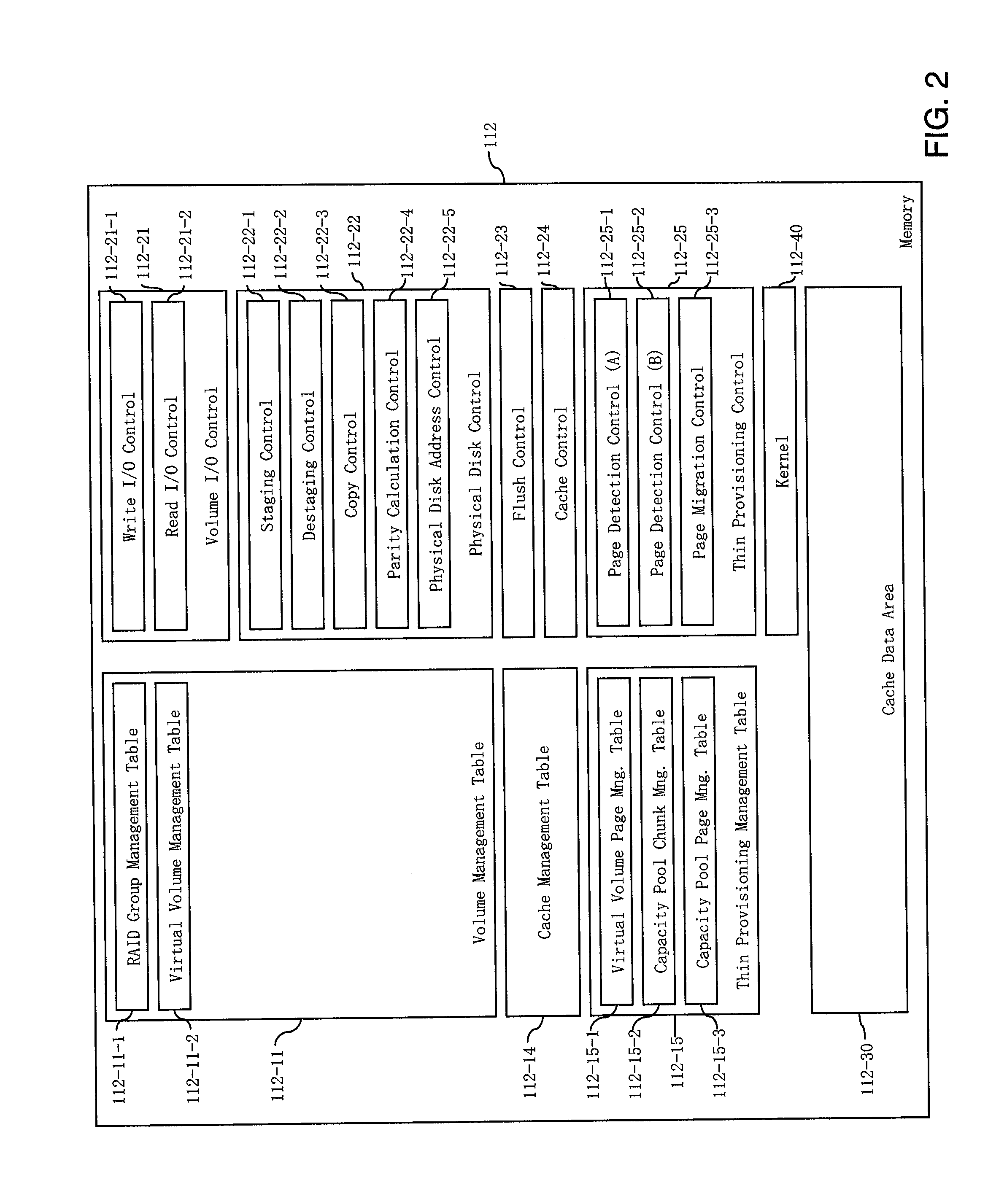
[0056]FIG. 2 illustrates an example of a memory 112 in the storage subsystem 100 of FIG. 1 according to a first embodiment of the invention. The memory 112 includes a Volume Management Table 112-11 that has a RAID Group Management Table 112-11-1 for the physical structure management for the disks 121 and those groups (FIG. 3), and a virtual Volume Management Table 112-11-2 for volume configuration management (FIG. 4). A Cache Management Table 112-14 (FIG. 8) is provided for managing the cache data area 112-30 and for LRU / MRU management. A thin Provisioning Management Table 112-15 includes a Virtual Volume Page Management Table 112-15-1 (FIG. 5) for reference management from a partition of a virtual volume to a partition of a capacity pool, a Capacity Pool Chunk Management Table 112-15-2 (FIG. 6) for resource management of a capacity pool and reference management from a capacity pool page to a virtual volume page, and a Capacity Pool Page Management Table 112-15-3 (FIG. 7) for resour...

second embodiment

[0085]FIG. 32 illustrates an example of a memory 112 in the storage subsystem 100 of FIG. 1 according to a second embodiment of the invention. Only changes from the first embodiment of FIG. 2 will be discussed. In FIG. 32, a Disk Management Table 112-11-3 (FIG. 33) is provided in place of RAID Group Management Table 112-11-1 of FIG. 2 for the physical structure management for the disks 121. FIG. 32 further shows alternative embodiments of the Virtual Volume Management Table 112-11-2′ (FIG. 34) in place of 112-11-2, Virtual Volume Page Management 112-15-1′ (FIG. 35) in place of 112-15-1, Capacity Pool Chunk Management Table 112-15-2′ (FIG. 36) in place of 112-15-2, Page Detection Control 112-25-1′ (FIG. 39) in place of 112-25-1, and Page Migration Control 112-25-3′ (FIG. 40) in place of 112-25-3.

[0086]FIG. 33 illustrates an example of a Disk or HDD Management Table 112-11-3 in the memory 112 of FIG. 32. The Disk Management Table 112-11-3 includes columns of the Disk Number 112-11-3-1...


PUM


Abstract

A storage system comprises a first storage device having a first plurality of hard disk drives and a first controller. The first controller stores data in the first plurality of hard disk drives by stripes. Each stripe includes M data and N parity data allocated to M+N hard disk drives of the first plurality of hard disk drives. A first hard disk drive includes data or parity data of both a first stripe of the stripes and a second stripe of the stripes, while a second hard disk drive includes data or parity data of only one of the first stripe or the second stripe. During data recovery involving failure of one of the first plurality of hard disk drives, the data in the failed hard disk drive is recovered for each stripe by calculation using data and parity data in other hard disk drives for each stripe.

Description

BACKGROUND OF THE INVENTION[0001]The present invention relates generally to data recovery in storage systems and, more particularly, to methods and apparatus for fast data recovery from storage device failure such as HDD (hard disk drive) failure. The invention demonstrates the agility of storage data recovery and ease of use of disk maintenance against disk failure.[0002]Currently, RAID (Redundant Array of Independent Disks) architecture is generally used to protect data from disk failure. For example, RAID5 and RAID 6 each make it possible to recover from one disk failure of the RAID Group. RAID5 and RAID6 are each more efficient for capacity than RAID1 or RAID10. When a disk failure occurs, the storage system recovers data to a reserved “spare disk.” It needs to access the entire area of healthy disks to recover data. The time to data recovery depends on disk capacity and disk throughput performance. Generally, the technology growth ratio of capacity is larger than that of throug...

Claims


Application Information

Patent Timeline
IPC IPC(8): G06F11/20
CPCG06F11/1076G06F11/1092
Inventor KAWAGUCHI, TOMOHIRO
Owner HITACHI LTD
Learn More