
Method and apparatus for in-store directions using visual or audio cues for current location determination

a technology of in-store directions and visual or audio cues, applied in the field of in-store direction systems, can solve the problems of wasting time and energy, difficult to remember where certain items are located, and difficult for shoppers to find

Inactive Publication Date: 2010-04-29
TATA CONSULTANCY SERVICES LTD
View PDF5 Cites 40 Cited by
  • Summary
  • Abstract
  • Description
  • Claims
  • Application Information

AI Technical Summary

Benefits of technology

[0007]This invention addresses the shortcomings associated with prior art as discussed above, by providing a method and apparatus to identify a shopper's current location in a retail store using only visual and audio cues in the store and then direct the shopper to the item he is looking for via a path in the store that balances the commercial objectives of the store with the convenience objectives of the shopper. The invention accomplishes this objective with the use of a mobile terminal that can communicate with a backend system via any commonly used wireless communication technology. The only requirement on the communication technology required for this invention is that it should be able to carry messages between the mobile terminal and the backend system or establish voice communication between the mobile terminal and the backend system. When a shopper requires a direction to a specific item in the store, the current location of the shopper is first determined by displaying or asking specific questions regarding visual or audio cues at the location where the shopper is

Problems solved by technology

This makes it very difficult and time consuming for shoppers to find the item they are looking for in such large stores.
Even for regular shoppers, it is difficult to remember where certain items are located.
As a result, shoppers typically move from aisle to aisle across the length and breadth of the store looking for certain items, thereby wasting time and energy.
For retailers, this affects the throughput of the stores since shoppers take more time shopping for a given number of items.
Retailers also miss the opportunity to gainfully make use of the time that shoppers spend in moving from one item to another since the retailers do not have a way of communicating to the shoppers when the shoppers are preoccupied with searching for their desired item.
Use of radio based or magnetic tagging techniques as in the above prior art to determine the location of the shopper in a store is costly and complicated in terms of the infrastructure required to support such location determination.
Use of scanners in the handheld terminals to scan the UPC code on the products also requires specialized mobile terminals, is also costly, and generally not available on the devices usually carried by the shoppers.
Even if their mobile phones support short-range wireless communication radio devices such as Bluetooth, enabling them upon entry to the store, pairing them with the store's transmitters and disabling them afterwards is cumbersome, aside from the infrastructure cost of positioning Bluetooth transmitters around the store.
Use of long-range location technologies such as Global Positioning Satellite (GPS) or Cellular-based location determination is not possible within stores since the accuracy of such systems in enclosed areas is not sufficient to provide the precise location and direction determination needed within stores.
This may not be optimal from the perspective of commercial objectives of the store and even the convenience objectives of the shopper, especially when the shopper doesn't have a pre-configured shopping list.

Method used


Image

  • Method and apparatus for in-store directions using visual or audio cues for current location determination
  • Method and apparatus for in-store directions using visual or audio cues for current location determination
  • Method and apparatus for in-store directions using visual or audio cues for current location determination

Examples


Embodiment Construction

[0024]A preferred embodiment of this invention will be described below. It is to be understood that persons of skill in the appropriate arts may modify this invention as described below and yet achieve the favorable results of this invention. In this sense, the following description is to be considered a broad, teaching disclosure and not as limiting upon this invention.

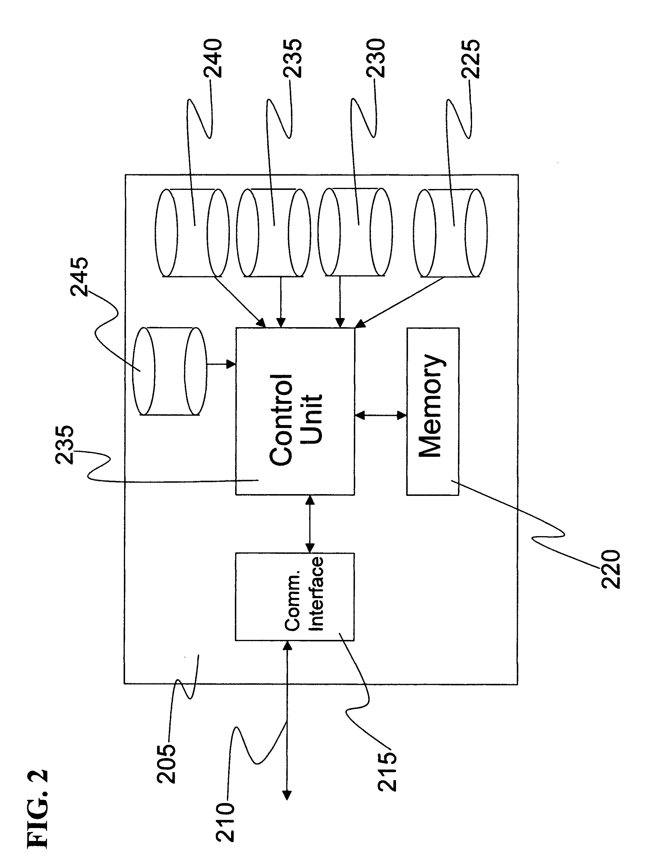
[0025]FIG. 1 presents a simplified semi-schematic block diagram of a mobile terminal operable in accordance with this invention. The mobile terminal 105 can be a handheld terminal such as a mobile phone belonging to the shopper or it could be a handheld device provided by the retail store to shoppers when they enter the store. The mobile terminal 105 may also be mounted on a shopping cart either on a permanent basis or in a temporarily detachable mode. As illustrated in FIG. 1, the mobile terminal consists of a display 110 that is used to display system responses and messages to the shopper. The mobile terminal also ...


PUM


Abstract

The present invention relates in general to in-store direction systems, and more specifically to a method and apparatus that determine the current physical location of a given shopper in the store using only visual or audio cues in the store; and then provide a path from the shopper's current location to an item the shopper is looking for, while taking into account commercial objectives of the store in addition to the convenience of the shopper. The apparatus as in this invention comprises just the shopper's mobile terminal and a backend system. This invention avoids the use of radio-frequency based location detectors within the store and hence avoids capital costs associated with those. The interaction between the mobile terminal and the shopper is carried out using one of a plurality of methods including application packets, SMS / MMS, or voice. Once the current location of the shopper and the location of the item to which the shopper wants to go to is determined, the path between the two is selected to include locations where items are being promoted or items that are related to the item the shopper is seeking are located. The path displayed on the mobile terminal is annotated with the location of such promoted and related items.

Description

CROSS-REFERENCE TO RELATED APPLICATIONS[0001]I hereby claim priority to my earlier filed Provisional patent application with Application No. 61 / 197,659 with filing-or-371(c) Date: Oct. 29, 2008BACKGROUND OF THE INVENTION[0002]This invention relates in general to in-store direction systems, and more specifically to a method and apparatus that determine the current physical location of a given shopper in the store using only visual or audio cues in the store; and then provide a path from the shopper's current location to an item the shopper is looking for, while taking into account commercial objectives of the store in addition to the convenience of the shopper.[0003]Retail stores around the world have been increasing in size. Average retail stores in the US are tens of thousands of square foot in floor area and can carry tens of thousands of items. This makes it very difficult and time consuming for shoppers to find the item they are looking for in such large stores. Even for regular...

Claims


Application Information

Patent Timeline
IPC IPC(8): G06Q30/00G06Q10/00G01C21/00
CPCG01C21/20G06Q90/20G06Q30/02
Inventor RAMASWAMY, SATYANARAYANAN
Owner TATA CONSULTANCY SERVICES LTD
Learn More