Wireless Transmission Method, Apparatus, And System
- Summary
- Abstract
- Description
- Claims
- Application Information
AI Technical Summary
Benefits of technology
Problems solved by technology
Method used
Image
Examples
first embodiment
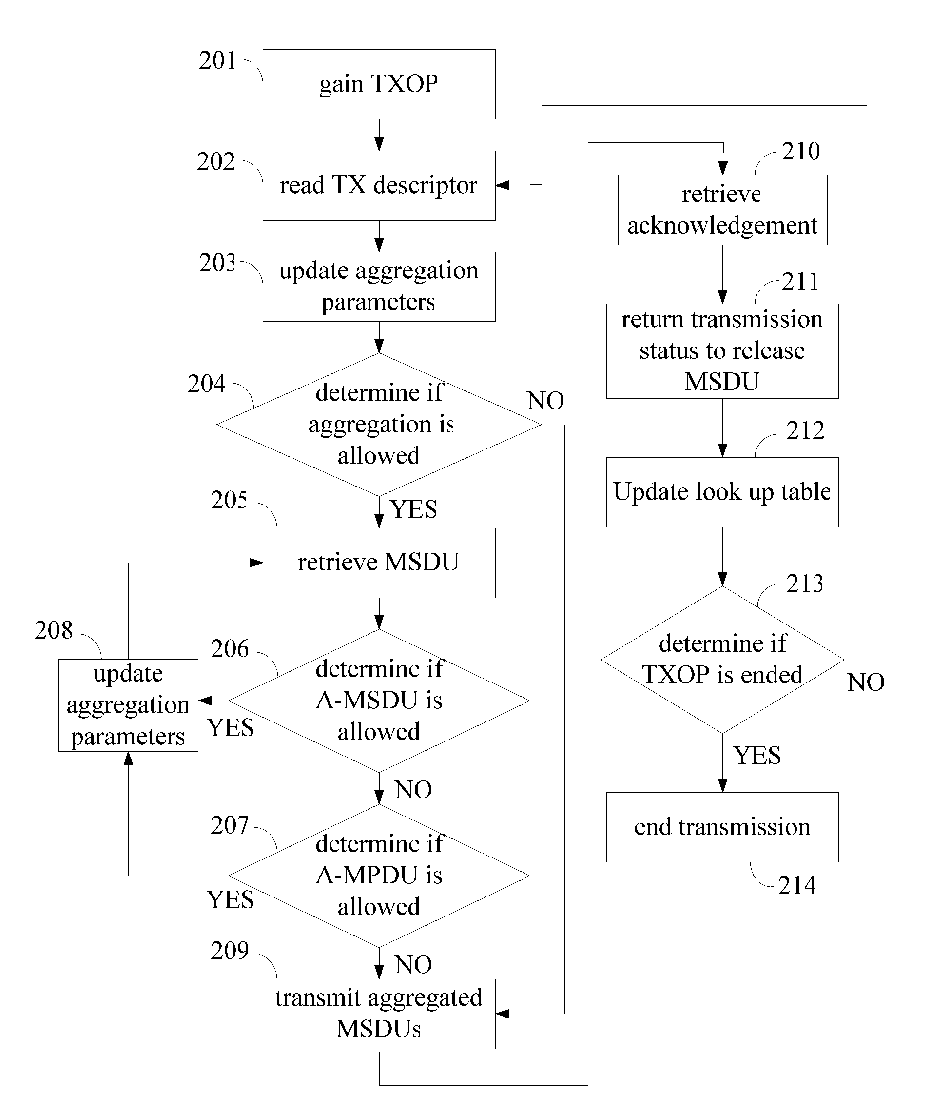
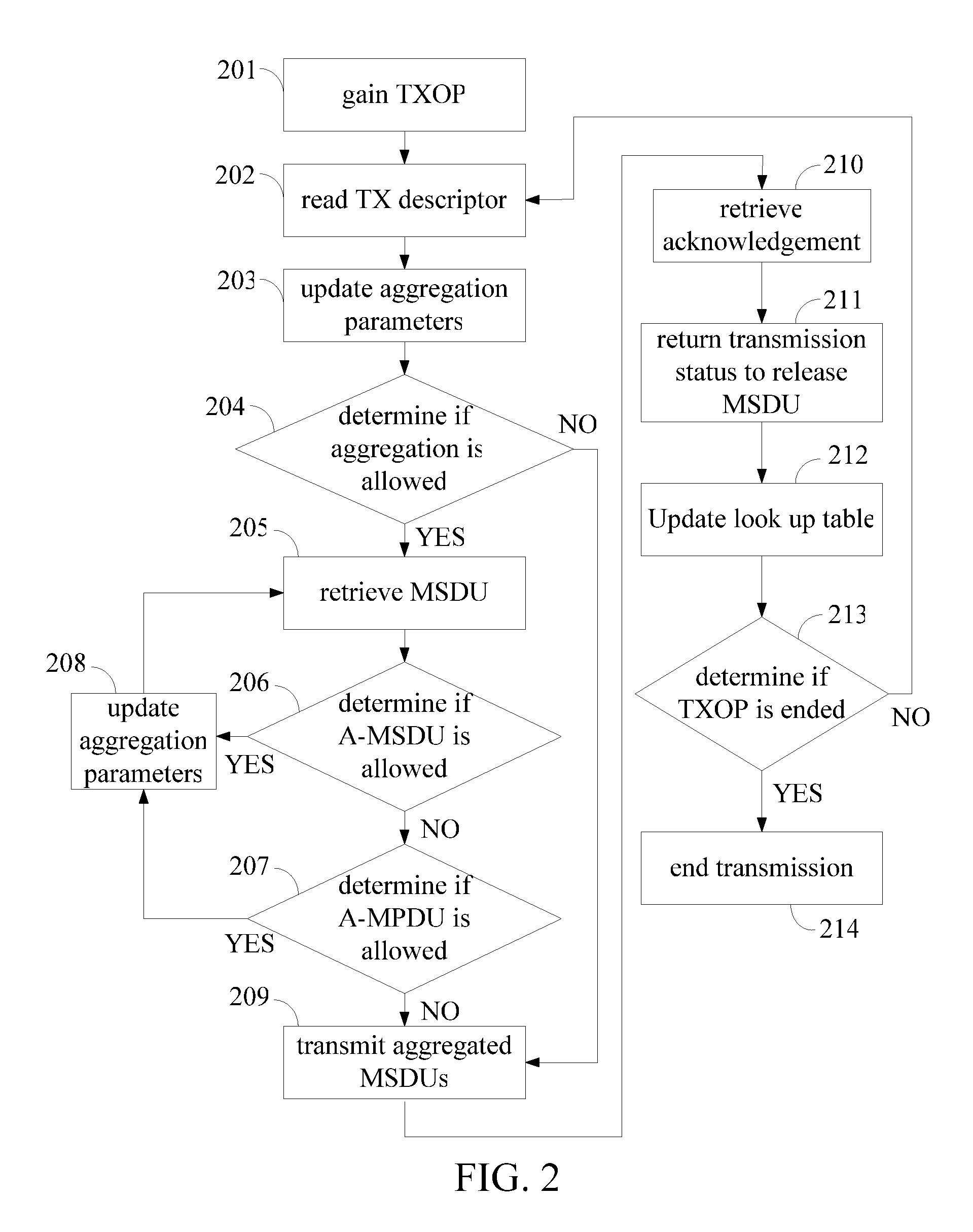
[0032]the present invention is a method performed in the second layer for transmitting data from a first layer to a third layer. FIG. 2 shows a flow chart of this method. In step 201, a TXOP is gained. The data units are in frame format and are denoted as MSDU, A-MSDU, MPDU, and A-MPDU. In step 202, a TX descriptor is read. The TX descriptor comprises the attributes and address of the data units. The address points to the location of a memory storing the data units, and the data units are unacknowledged in step 202. In step 203, aggregation parameters in a look up table are updated. In this embodiment, the aggregation parameters comprise MSDU-count, Total-length, A-MSDU-bitmap, and ACK-bitmap. The look up table is an aggregation scoreboard. In step 204, processing of the aggregation is determined. If the determination is YES, then step 205 is executed and another TX descriptor is read to retrieve an MSDU for aggregation according to the ACK-bitmap, wherein the ACK-bitmap records the...
third embodiment
[0045]In the third embodiment, all five MSDUs cannot be transmitted when underflow occurs. By padding the transmission, four out of the five MSDUs can still be transmitted, keeping the TXOP available.
[0046]FIG. 5(a) and FIG. 5(b) are diagrams of the padding transmission of the aggregated MPDUs of the fourth embodiment. In the fourth embodiment, the space of the buffer in the second layer is smaller than the length of one MSDU. The fourth embodiment assumes that a TXOP is gained and five MPDUs 51, 52, 53, 54, 55 are aggregated for transmission.
[0047]In FIG. 5(a), an A-MPDU 50 comprises five MPDUs 51, 52, 53, 54, 55 for transmission. If there is no underflow, the five MPDUs 51, 52, 53, 54, 55 can be transmitted to the third layer. FIG. 5(b) shows transmission with underflow. At time t1, the MPDU151 is incompletely transmitted, which means that parts of the MPDU151 stored in the buffer run out and underflow occurs. At this time, the transmission of MPDU151 is skipped, and the residual ...
fourth embodiment
[0048]In the fourth embodiment, when each time underflow occurs, the current MSDU is skipped. By padding the residual space of the skipped MSDU, other MSDUs can still be transmitted, keeping the TXOP available.
[0049]A fifth embodiment of the present invention is shown in FIG. 6, which is a wireless transmission apparatus of the second layer for transmitting data from a first layer to a third layer. The wireless transmission apparatus comprises a receiver 601, a processor 603, a selection circuit 605, an update circuit 607, a pad circuit 609, a buffer 611, and a look up table 613. The receiver is configured for retrieving information related to unacknowledged data units from the first layer; thus, the receiver reads information 602 contained in a TX descriptor 615. The processor 603 is configured for aggregating the unacknowledged data units according to the information 602, wherein the unacknowledged data units are selected by the selection circuit 605. The information 602 is also a...
PUM
 Abstract
Description
Claims
Application Information
 - R&D
- Intellectual Property
- Life Sciences
- Materials
- Tech Scout
- Unparalleled Data Quality
- Higher Quality Content
- 60% Fewer Hallucinations
Browse by: Latest US Patents, China's latest patents, Technical Efficacy Thesaurus, Application Domain, Technology Topic, Popular Technical Reports.
© 2025 PatSnap. All rights reserved.Legal|Privacy policy|Modern Slavery Act Transparency Statement|Sitemap|About US| Contact US: help@patsnap.com


