Eureka AIR delivers breakthrough ideas for toughest innovation challenges, trusted by R&D personnel around the world.

Arrangement for cooling of an electrical machine

Inactive Publication Date: 2010-04-29
SIEMENS AG
View PDF11 Cites 13 Cited by
  • Summary
  • Abstract
  • Description
  • Claims
  • Application Information

AI Technical Summary

Benefits of technology

[0022]The inventive step lies in the combination of coolant channels and support structure, which ensures both low weight and good thermal contact.

Problems solved by technology

This cooling method has the disadvantage, that large gas-to-air or gas-to-water heat exchangers are required.
Furthermore considerable power is required to circulate the cooling medium.

Method used


Image

  • Arrangement for cooling of an electrical machine
  • Arrangement for cooling of an electrical machine

Examples

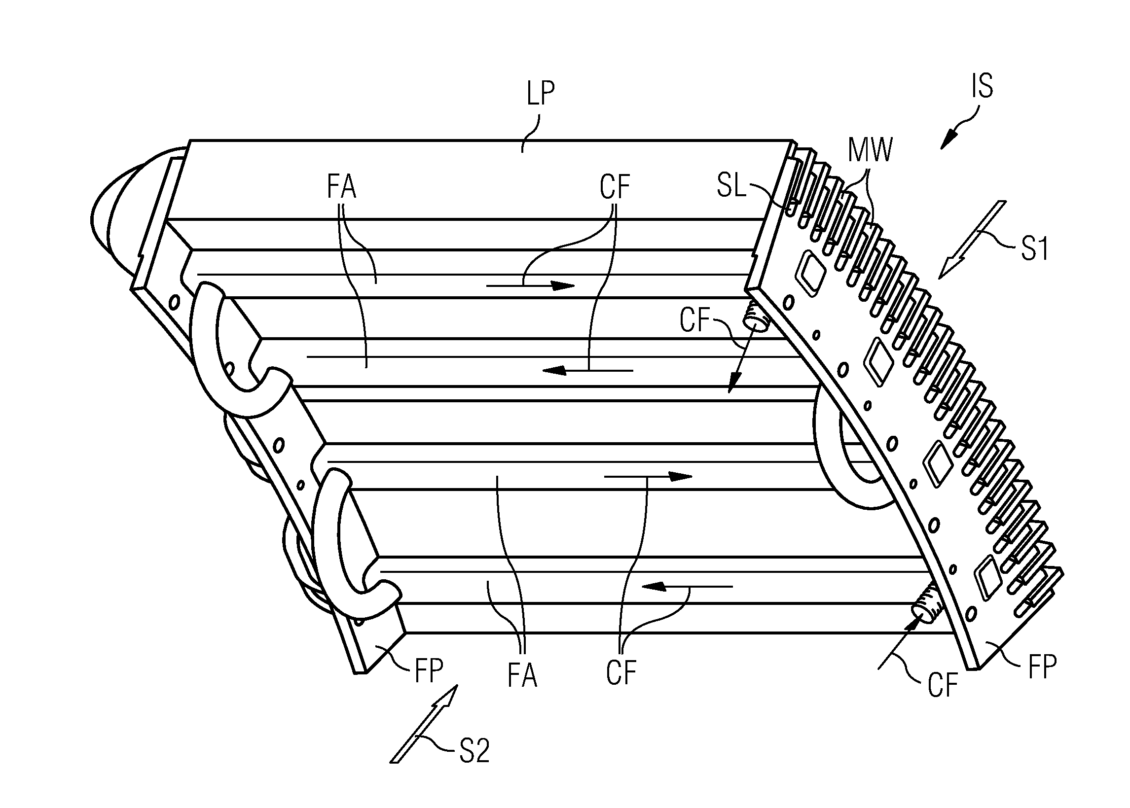

Embodiment Construction

[0025]That kind of generator is normally totally enclosed by a shell or by a housing to avoid the influence of harsh ambient conditions to components of the generator.

[0026]The generator in this example shows an inner stator and an outer rotor, while there is a gap with air between them.

[0027]The inner stator IS, which is shown here partly, consists of a number of laminate plates LP made of metal.

[0028]The laminate plates LP show on a first side Si a number of slots SL, so the slots SL are forming a number of channels on the first side S1.

[0029]Within the slots SL there are metal windings MW, which are used to build electrical coils of the inner stator IS. Shown here is a so called “single-layer winding” with one metal-winding per slot SL.

[0030]Next to the metal-windings MW there is the air-gap, while the outer rotor—not shown here—interacts with the metal windings MW of the inner stator IS.

[0031]On a second side S2 of the laminate plates LP there are a number of fixing-arrangements...


PUM


Abstract

In one aspect, an arrangement is provided. An electrical machine includes elements generating heat while the electrical machine is at work. The elements include at least one fixing-arrangement to support an element-structure. The fixing-arrangement is hollow to carry a cooling fluid which allows a transfer of the heat away from the elements.

Description

CROSS REFERENCE TO RELATED APPLICATIONS[0001]This application claims priority of European Patent Office application No. 08018802.2 EP filed Oct. 28, 2008, which is incorporated by reference herein in its entirety.FIELD OF INVENTION[0002]The invention relates to an arrangement for cooling of an electrical machine.BACKGROUND OF INVENTION[0003]In a preferred embodiment it relates to the cooling of an electrical machine which, is totally enclosed by a shell or housing.[0004]Electrical machines need cooling in order to dissipate the heat, which is generated during operation by ohmic resistance, iron hysteresis, etc.[0005]Small electrical machines may be “surface cooled”, but due to the fact that large machines have relatively smaller surfaces per power rating and heat generation, this arrangement will not work for large machines[0006]When installed under indoor conditions in a normal, dry atmosphere, electrical machines may be not enclosed by a housing, so the cooling can be done by the ...

Claims


Application Information

Patent Timeline
IPC IPC(8): H02K9/19H02K9/00
CPCH02K1/20H02K9/19H02K2213/12Y02E10/725H02K7/1838H02K9/22Y02E10/72H02K9/227H02K9/197
Inventor ERIKSEN, UFFESTIESDAL, HENRIK
Owner SIEMENS AG
Why Eureka
Eureka Blog
Learn More