
Vertical axis variable geometry wind energy collection system

a technology of wind energy collection and variable geometry, applied in the direction of renewable energy generation, electric generator control, machines/engines, etc., can solve the problems of prohibitive designs for individuals or small electric cooperatives, additional costs associated with providing the necessary transmission infrastructure to connect the output of these devices, and the threshold of wind speed of devices of this type is relatively high before operation can be initiated

Inactive Publication Date: 2010-04-15
AARON MICHAEL SCOTT
View PDF5 Cites 18 Cited by
  • Summary
  • Abstract
  • Description
  • Claims
  • Application Information

AI Technical Summary

Problems solved by technology

The cost of installation and operation of such huge structures make such designs prohibitive for individuals or small electric cooperatives.
There is an additional cost associated with providing the necessary transmission infrastructure to connect the output of these devices to the existing grid as these devices are typically located far from the grid.
Conversely devices of this type have a relatively high threshold of wind speed before operation can be initiated due to the large inertial and frictional forces associated with startup.
The size of the structures associated with this type of design has been found to pose a hazard to wildlife as well as being unsightly to the landscape.
In addition, there has been some speculation that the harmonic frequencies generated by the high tip speed of the turbines may be harmful to humans and wildlife.

Method used


Image

  • Vertical axis variable geometry wind energy collection system
  • Vertical axis variable geometry wind energy collection system
  • Vertical axis variable geometry wind energy collection system

Examples


Embodiment Construction

—FIGS. 1 THRU 44, 49A THRU 61—PREFERRED EMBODIMENT

[0185]The description of the apparatus may best be made by detailing the three main assemblies in turn and showing their connectivity to each other as logical opportunity permits.

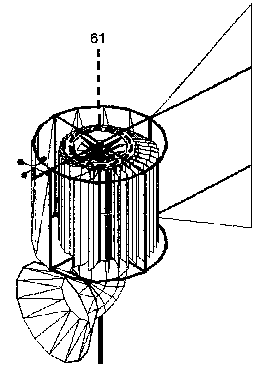
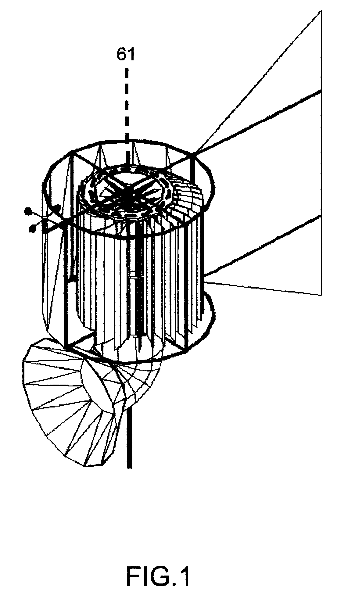
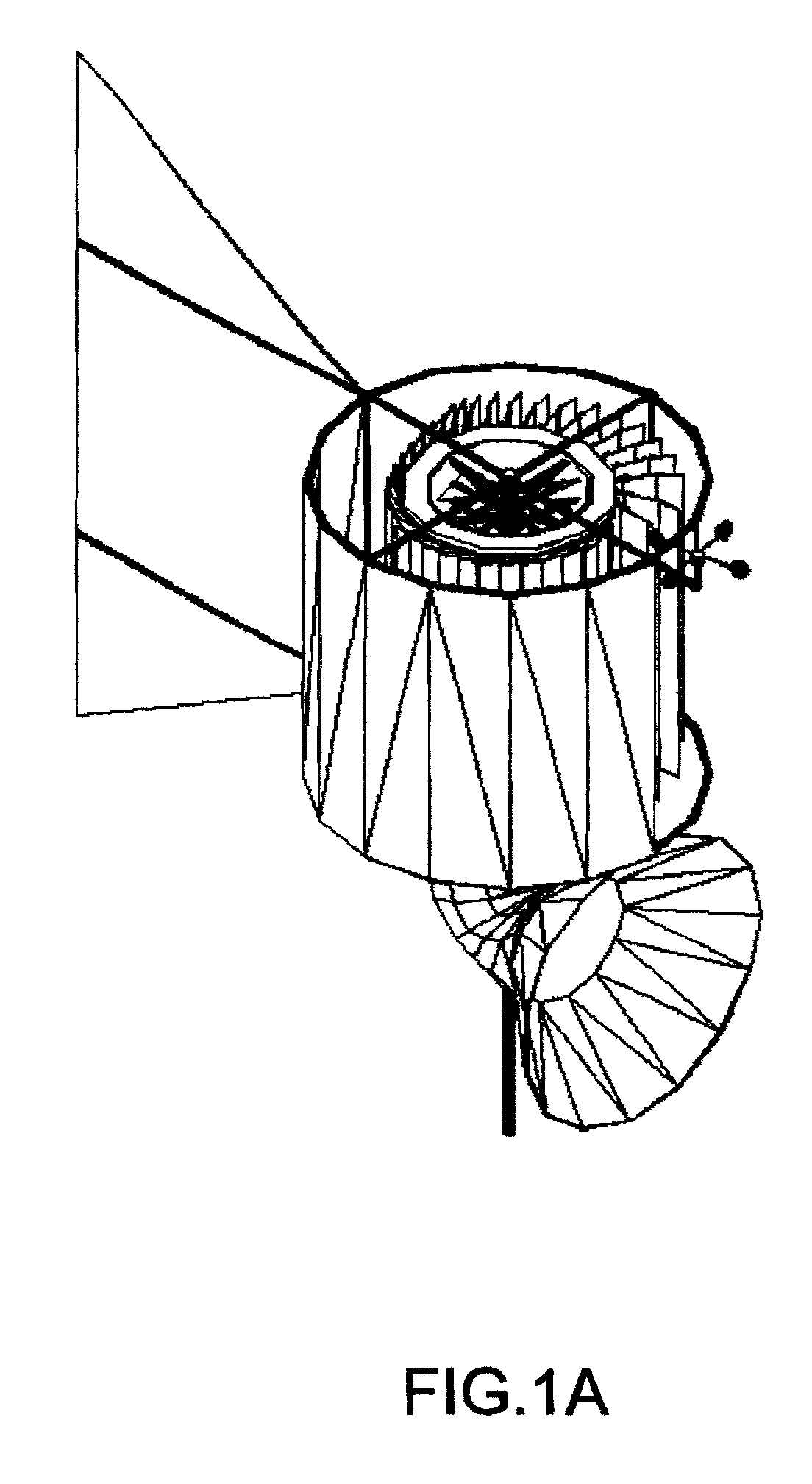
[0186]FIGS. 1 and 1A show perspective views of the apparatus.

[0187]FIGS. 2, 3, 4, 5, 6, and 7 show right, left, front, rear, top, and bottom side orthogonal views respectively of the apparatus.

[0188]FIGS. 8, 9, and 10 show perspective views of the static assy. 101, rotors assy. 501, and directional windshield assy. 1001 respectively.

[0189]FIG. 11 shows a perspective view of the static assy. 101 without generator stator subassemblies 117 and 119 installed. The subassemblies depicted in FIG. 11 are a support structure for static assy. 102, and upper bearing for directional windshield assy. 103, an upper bearing for rotors assy. 105, a lower bearing for rotors assy. 111, a generator stator support structure 109, a lower bearing for directional windshield assy. ...


PUM


Abstract

A device to convert the kinetic energy of wind into kinetic energy in the form of a rotating mass (FIG. 9) and to then selectively harvest and convert the kinetic energy of the rotating mass into electrical energy using both permanent magnet and electromagnet generators (FIG. 33). The conversion of the kinetic energy of wind into mechanical kinetic energy of the rotating mass is maximized through mechanical means by varying the physical moment of inertia of the rotating mass programatically based upon real time sensor data (FIG. 27A,27B). The conversion of the kinetic energy of the rotating mass into electrical energy is maximized through the programatical control of the field coil current of the electromagnet generator based upon real time sensor data (FIG. 62).

Description

CROSS-REFERENCE TO RELATED APPLICATIONS [0001]Not ApplicableFEDERALLY SPONSORED RESEARCH [0002]Not ApplicableSEQUENCE LISTING OR PROGRAM [0003]Not ApplicableBACKGROUND OF THE INVENTION[0004]1. Field of Invention[0005]This invention relates to a device with which to efficiently capture wind energy and transform it into electrical power.[0006]2. Background of the Invention[0007]Wind has been utilized by man throughout history for power to mill grains, to power transmissions used in industrial processes, and to power transportation. With the current environment of energy supply from fossil based fuels becoming more scarce and expensive, wind power is being considered increasingly as an alternative means to provide electrical power.[0008]At present the prevailing design for a typical wind generator employs the classical wind turbine whereby a nacelle assembly housing the generator and reduction gears is mounted atop a tall tower with large turbine blade structures connected to the prime...

Claims


Application Information

Patent Timeline
Patent Type & Authority Applications(United States)
IPC IPC(8): F03D3/06F03D9/00
CPCF03D3/005F03D3/0436F05B2220/7068Y02E10/72Y02E10/74F03D1/04F05B2240/13F03D3/0445F03D9/25F03D13/10
Inventor AARON, MICHAEL SCOTT
Owner AARON MICHAEL SCOTT
Learn More