Developing device and image forming device

Inactive Publication Date: 2010-04-15
KONICA MINOLTA BUSINESS TECH INC
View PDF0 Cites 3 Cited by
  • Summary
  • Abstract
  • Description
  • Claims
  • Application Information

AI Technical Summary

Benefits of technology

[0013]To this end, a first object of the present invention is to provide an image forming device which is capable of forming an electrostatic latent image on an electrostatic latent image carrier and develop the electrostatic latent image to form a toner image, the image forming device being a mono-component developing device used for development of the electrostatic latent image, comprising a developer carrier roller which is rotationally driven and a toner thin layer forming member which is brought into contact with this roller, the roller being formed in the shape of an inverted crown which is concave at the central portion in the direction of the rotation shaft (the direction of the rotation axis of the developer carrier roller), the image forming device being capable of maintaining the clearance between the developer carrier roller and a drum photoreceptor to a constant value and carrying out good image formation, and inhibiting spillage, scattering and leakage of the toner to prevent the inside of the image forming device from being contaminated even if the developer carrier roller has the shape of an inverted crown.
[0014]A second object of the present invention is to provide an image forming device which is capable of forming an electrostatic latent image on an electrostatic latent image carrier and develop the electrostatic latent image by a developing device to form a toner image, maintaining the clearance between the developer carrier roller and the drum photoreceptor to a constant value and carrying out good image formation, and inhibiting contamination of the inside of the image forming device by spillage, scattering and leakage of the toner even if the developer carrier roller has the shape of an inverted crown.
[0017]In this developing device, the developer carrier roller has the shape of an inverted crown, and a change in curvature is large in the starting point (initial point) of this shape of an inverted crown. Therefore, the contacting state of the toner thin layer forming member and the developer carrier roller is unstable and a gap is formed therebetween. However, the starting point of this shape of an inverted crown exists outside the toner thin layer region. That is, the starting point of the shape of an inverted crown is positioned further outside (end side) in the direction of the rotation shaft than the toner thin layer region. In the toner thin layer region, the contacting state of the toner thin layer forming member and the developer carrier roller is stable (the contacting and nipping state is stable), and therefore spillage of the toner from the toner thin layer forming member can be inhibited.
[0020]The image forming device according to the present invention comprises the developing device according to the present invention as a developing device, and this developing device can maintain the clearance between the developer carrier roller and the electrostatic latent image carrier constant and allow good image formation, and at the same time inhibit spillage, scattering and leakage of the toner even if the developer carrier roller has the shape of an inverted crown, and thus can prevent contamination of the inside of the image forming device.

Problems solved by technology

Accordingly, the developing roller is pushed in the direction of the drum photoreceptor by the contacting pressures of the toner supply roller and thin layer forming blade, whereby warping occurs in the developing roller, which prevents maintaining the predetermined clearance.
As a result, a difference in developed density is disadvantageously created between the central portion and both ends of the developing roller.
In a developing roller having the shape of an inverted crown, When the starting point (initial point) of this shape of an inverted crown is present in a region in which an image is formed (in the region where a toner thin layer is present), a change in curvature at the starting point is large, and therefore the contacting state of the roller and the thin layer forming blade becomes unstable even if the thin layer forming blade is formed from an elastic material, which forms a gap therebetween.
This problem not only occurs when an elastic rubber roller (a roller around the periphery of which an elastic rubber layer is provided as the core) is used as the developing roller, but, for example, becomes especially noticeable when a hollow aluminium blast roller (coreless hollow metal roller mainly composed of aluminium having unevenness formed on its outer peripheral surface by the shot blast method to improve its ability to carry toner) is employed.
Such a gap may lead to spillage of the toner from the thin layer forming blade; scattering of the toner from a diselectrifying member which is sometimes in contact with the developing roller; and insufficient leakage prevention of the toner by the toner sealing member disposed for both ends of the developing roller.
H6-258933, no consideration is paid to the fact that the contacting state of the thin layer forming blade and the developing roller becomes unstable because of such a shape of an inverted crown.
Accordingly, in the image forming device disclosed in this publication, the toner may spill into the image forming device, scatter and leak, and thus may contaminate the inside of the image forming device.

Method used


Image

  • Developing device and image forming device
  • Developing device and image forming device
  • Developing device and image forming device

Examples


Embodiment Construction

[0029]An image forming device comprising a developing device according to an embodiment of the present invention will be described in detail below with reference to accompanying drawings. The developing device according to an embodiment of the present invention can be employed in a plurality of types of image forming devices by making some modification depending on the type of image forming device. Accordingly, a typical image forming device will be described first. In the description below, identical parts are denoted by identical numerals. Their names and functions are also identical. Therefore, the detailed description of them is not repeated.

[0030][Overall Constitution of Image Forming Device (Four-Cycle Type)]

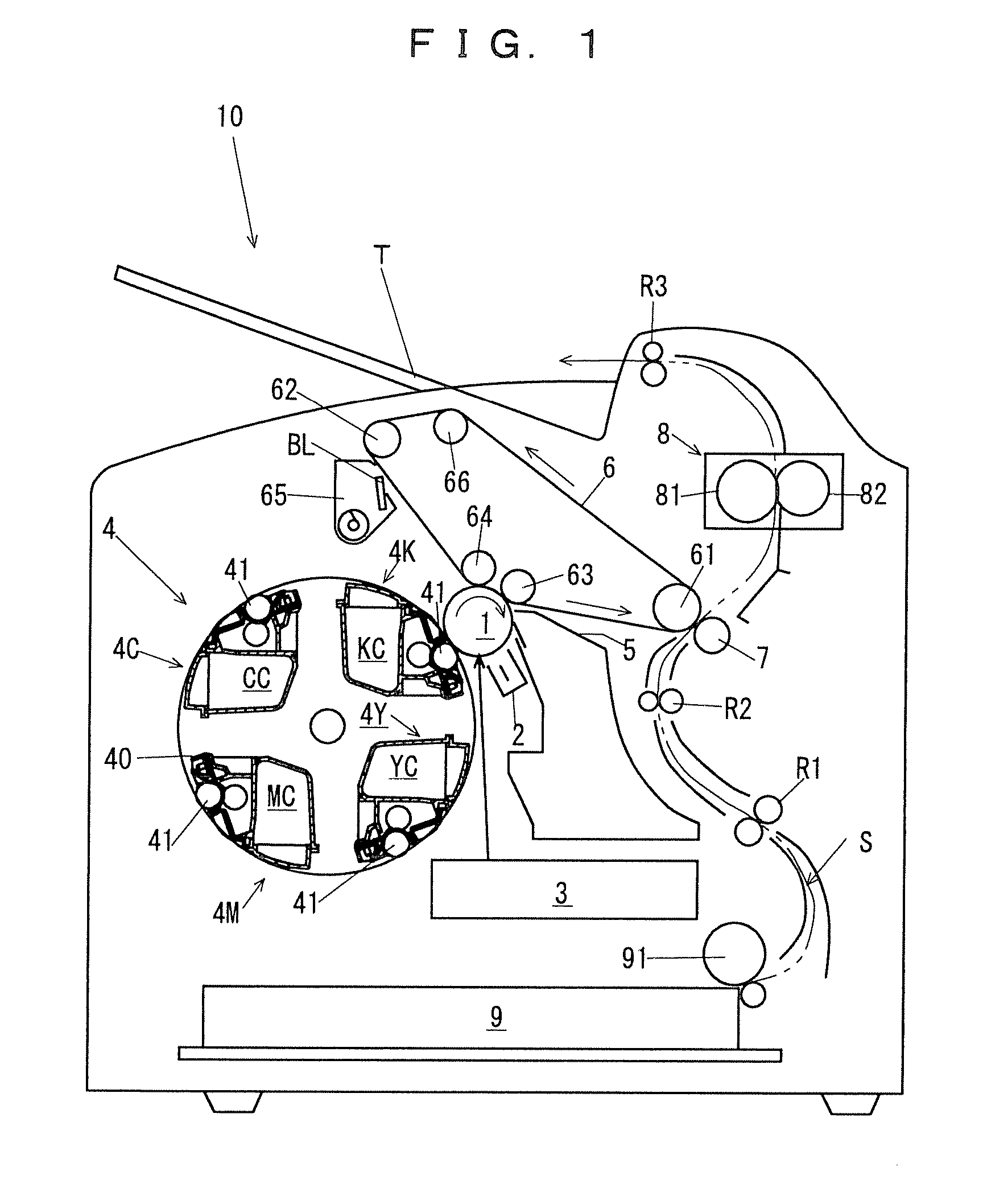
[0031]FIG. 1 shows a developing device 10 comprising an image forming device according to this embodiment. The image forming device 10 of FIG. 1 is a so-called four-cycle type full-color image forming device. In the description below, the recording medium is recording pape...


PUM


Abstract

A developing device used for forming a toner image by developing the electrostatic latent image on an electrostatic latent image carrier in an image forming device, comprises a developer carrier roller which is rotationally driven, and a toner thin layer forming member which is brought into contact with the developer carrier roller, wherein the developer carrier roller is formed in the shape of an inverted crown which is concave at the central portion in the direction of the rotation axis, and a starting point of the shape of the inverted crown is positioned further outside in the direction of the rotation axis than toner thin layer region formed by the toner thin layer forming member.

Description

CROSS-REFERENCE TO RELATED APPLICATION[0001]This invention is based on Japanese Patent Application No. 2008-262444 filled with Japan Patent Office on Oct. 9, 2008, the entire content of which is hereby incorporated by reference.BACKGROUND OF THE INVENTION[0002]1. Field of the Invention[0003]The present invention relates to a developing device used for an image forming device which forms a toner image, such as a copying machine, a printer, a facsimile machine or a multifunctional machine which is a combination of two or more of these devices, especially to a technique for preventing spillage and scattering of a toner in a mono-component developing device. Moreover, the present invention also relates to an image forming device comprising a developing device.[0004]2. Description of the Related Art[0005]In an image forming device which forms a toner image such as a copying machine, a printer, a facsimile machine or a multifunctional machine which is a combination of two or more of these...

Claims


Application Information

Patent Timeline
IPC IPC(8): G03G15/08
CPCG03G15/0818
Inventor NISHI, MASAYUKINAKANO, MUNENORI
Owner KONICA MINOLTA BUSINESS TECH INC
Why Eureka
Try Eureka