
Grip with bipod

Inactive Publication Date: 2010-04-08
FAB MFG & IMPORT OF INDAL EQUIP
View PDF16 Cites 38 Cited by
  • Summary
  • Abstract
  • Description
  • Claims
  • Application Information

AI Technical Summary

Problems solved by technology

A disadvantage of the bipod of Moody is that the legs are deployed together with one another and extend from the bottom of the grip.
Furthermore, the legs are limited to the same length, since there is only one piston mechanism for both of the legs.

Method used


Image

  • Grip with bipod
  • Grip with bipod
  • Grip with bipod

Examples


Embodiment Construction

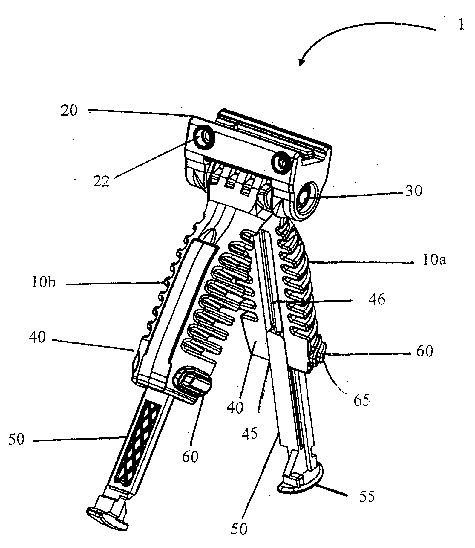
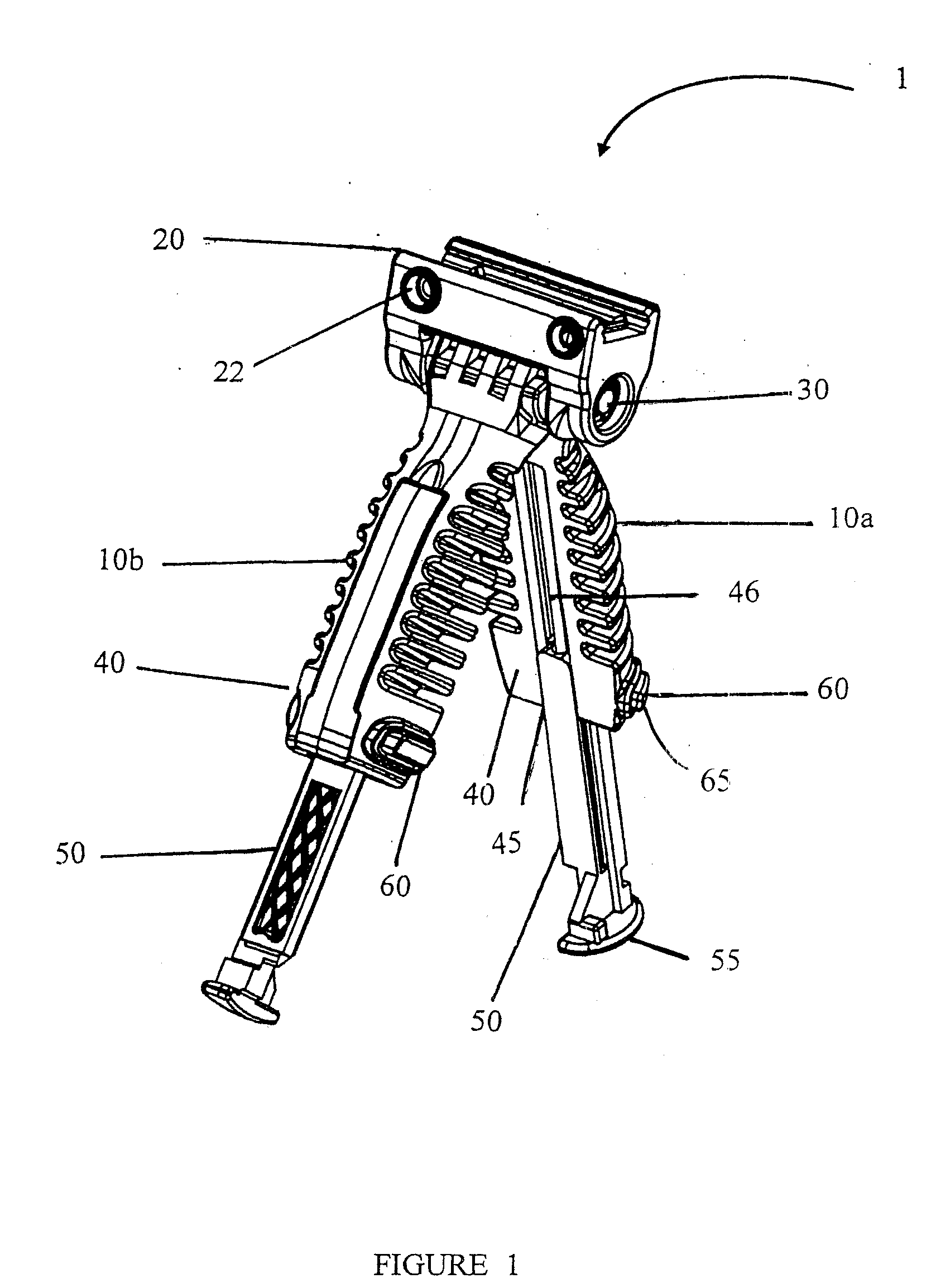
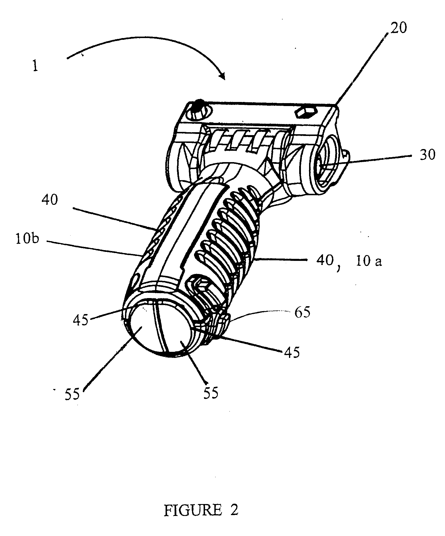
[0024]The present invention relates to a combination of a grip and a bipod formed of hinged monopods. In the deployed positions, the monopods act as a bipod, which can be used to position, support, and stabilize a device, such as a firearm, camera and so on, which needs stabilization when aimed at a target. When the monopods are in the closed position, they form a hand grip, which can be used to support and control the device on which it is mounted. Preferably, the grip is ergonomically shaped to provide a comfortable and secure grip.

[0025]The grip, according to the present invention, includes at least two hinged monopods, each having an independent telescopic structure. In the closed position, the monopods together form a shaped hand grip. Each of the monopods defines a head portion having an arched portion. The head portion further includes first and second shoulder portions, one shoulder portion defined on each side of the arched portion. The grip further includes a hinge housing...


PUM


Abstract

A grip including at least two hinged monopods, each having an independent leg extension, the monopods in the closed position forming a hand grip, and a mounting assembly for mounting the grip on a device, and a method for forming the grip. Preferably, the leg extension includes a housing in each of the monopods and at least one spring biased leg telescopingly mounted in the housing.

Description

[0001]This application is a Continuation In Part of U.S. patent application Ser. No. 12 / 190604, and claims the benefit of U.S. Provisional Application No. 60 / 955,406, filed Aug. 13, 2007, the entire disclosures of which are incorporated herein by reference.FIELD OF THE INVENTION[0002]The present invention relates to bipods for firearms, cameras and other devices. More particularly the invention relates to a support grip which is also a bipod.BACKGROUND OF THE INVENTION[0003]A foregrip is a grip on the front of a firearm that can be used to help support the firearm, and prevents burns from the barrel during firing. The foregrip is preferably shaped for comfortable gripping with a hand, for example, having a rounded shape.[0004]A bipod is a device having two legs used to position, support, and stabilize a device which requires aiming, such as a firearm or a camera. Bipods may be independent devices for removable mounting on the device, or may be integrally formed therewith. Bipods wit...

Claims


Application Information

Patent Timeline
IPC IPC(8): F16M11/38
CPCF16M11/04F16M11/041F16M11/24F16M11/26F41G11/003F16M2200/04F41A23/10F41C23/16F16M13/00
Inventor FAIFER, SAGI
Owner FAB MFG & IMPORT OF INDAL EQUIP
Learn More