
Pipetting device

a pipetting device and pipetting technology, applied in the field of pipetting devices, can solve the problems of pipetting device metering volume, accompanied by a very high force expense, and inaccuracy of metering

Active Publication Date: 2010-04-08
EPPENDORF SE
View PDF29 Cites 18 Cited by
  • Summary
  • Abstract
  • Description
  • Claims
  • Application Information

AI Technical Summary

Benefits of technology

[0034]When using plastic materials, those mentioned above in particular, as a material of the friction partners lead screw nut—lead screw, the advantage of the present invention becomes particularly marked, namely that the friction between the friction partners is reduced through the other thread form of the further internal thread or external thread. As a metal, brass or stainless steel may be used e.g.
[0035]According to one embodiment, the torque for moving the lead screw in the lead screw nut is about 50 mNm at maximum, i.e. 55×10−3 Nm. Preferably, it is about 40 mNm at maximum. Tolerance caused deviations from the mentioned upper limits are possible.
[0036]The lifting rod can be arranged completely outside the lead screw. Preferably, the stop is formed by a front side of the lead screw or the lead screw nut. According to a preferred embodiment, the lead screw features a channel which partly accommodates the lifting rod. Further preferably, the channel extends through the whole lead screw, and the counter-stop and the driving means are arranged on different sides of the lead screw.
[0037]The driving means of the lifting rod is a drive motor, for instance. According to a preferred embodiment, the driving means of the lifting rod is an actuation button. The actuation button is preferably actuable against the action of a spring device, which shifts the lifting rod into a starting position upon release of load, in which the lifting rod is farthest away from the displacement chamber.
[0038]According to a further embodiment, the lead screw nut is stationary with respect to the displacement chamber, and the lead screw is screwable with respect to the lead screw nut.BRIEF DESCRIPTION OF THE VIEW OF THE DRAWINGS
[0039]The present invention will be explained in more detail by means of the attached drawings of examples of its realisation. In the drawings show:

Problems solved by technology

Due to manufacturing tolerances, the lead screw has a clearance in the nut, which may lead to metering inaccuracies.
However, they have the disadvantage that the adjustment of the metering volumes in pipetting devices of different magnitude, which differ in the adjustment ranges of their metering volumes (for instance, 0.5-10 μl, 10-100 μl, 100-1000 μl), is accompanied by a very high expense of force.
Namely, due to the thread friction decreasing with increasing thread steepness, the expense of force for adjusting the metering volume is greater at pipetting devices with small adjustment range than the expense of force for adjusting the metering volume at pipetting devices with great adjustment range.

Method used


Image

  • Pipetting device
  • Pipetting device
  • Pipetting device

Examples


Embodiment Construction

[0052]While this invention may be embodied in many different forms, there are described in detail herein a specific preferred embodiment of the invention. This description is an exemplification of the principles of the invention and is not intended to limit the invention to the particular embodiment illustrated

[0053]The designations “on top”, “on the bottom”, “horizontal”, “vertical” and “front”, “rear” are related to the orientation of the pipetting device in the drawings. In this, it is dealt with an orientation of the pipetting device in which a pipette tip connected to it is arranged with its tip opening at the bottom side, in order to pick up liquid from a vessel situated below the pipetting device, or to discharge it into such a vessel.

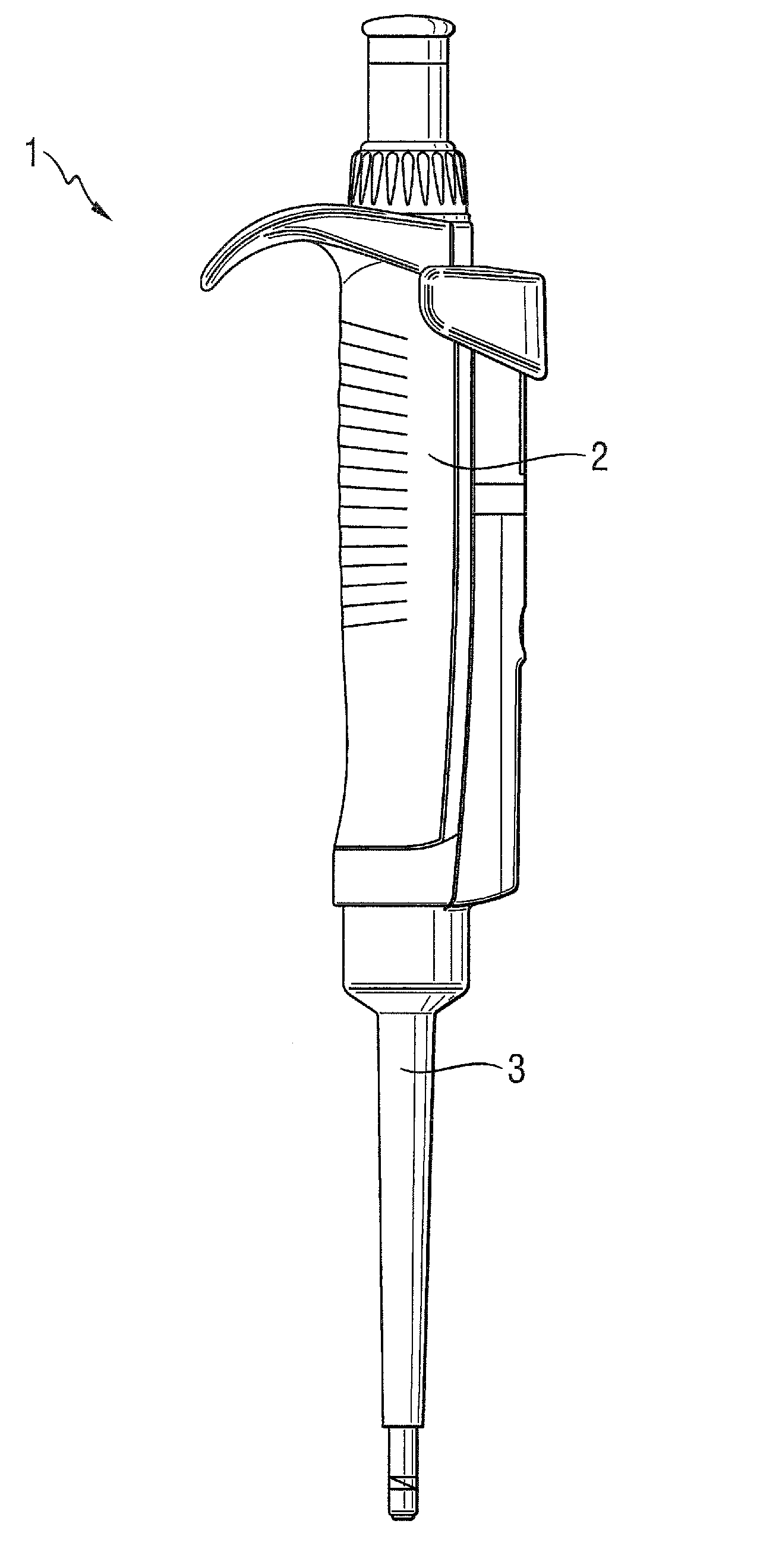
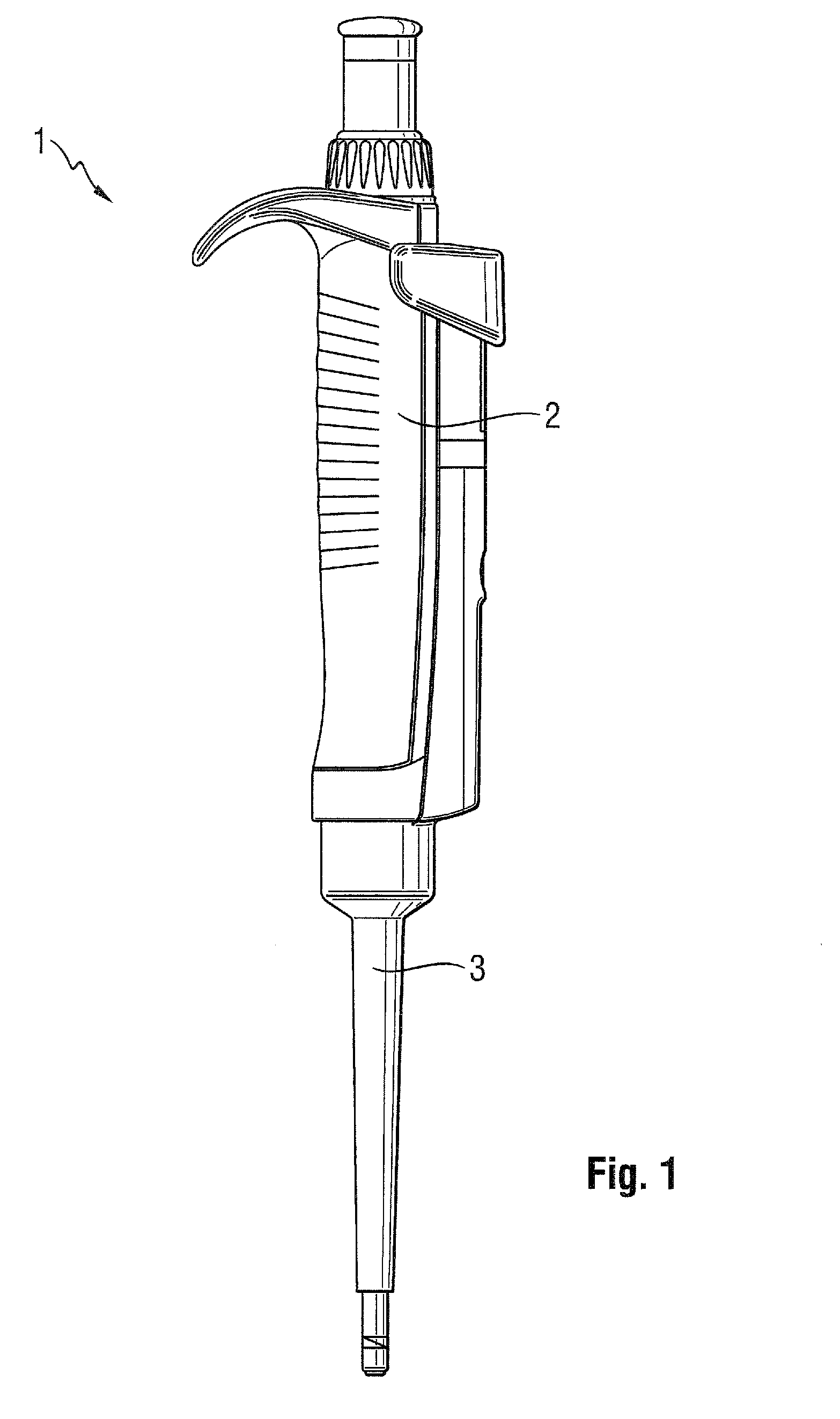
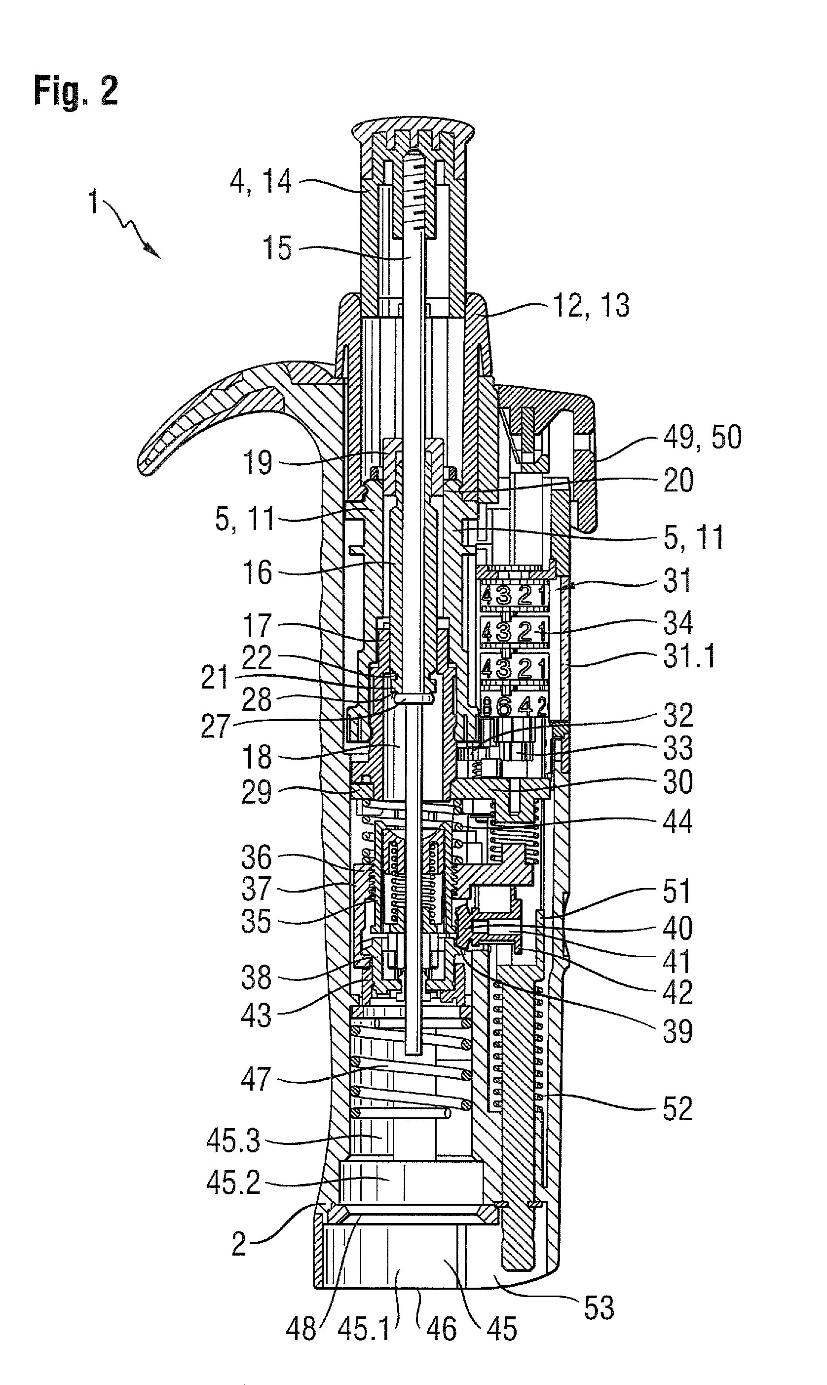
[0054]The pipetting device according to FIGS. 1, 2 and 8 has a longitudinal casing shaped to be a handhold, with an upper casing part 2 and a lower casing part 3.

[0055]According to FIG. 2, the upper casing part 2 features driving means 4 and adj...


PUM


Abstract

The present invention is related to a pipetting device with means for detachably connecting with at least one pipette tip, at least one displacement device, a driving device for driving a displacement member of the displacement device and an adjustment device with a lead screw nut and a lead screw for adjusting the metering volume.

Description

CROSS-REFERENCE TO RELATED APPLICATIONS[0001]This application is a non-provisional of 61 / 097,393 filed Sep. 16, 2008.STATEMENT REGARDING FEDERALLY SPONSORED RESEARCH[0002]Not applicable.BACKGROUND OF THE INVENTION[0003]The present invention is related to a pipetting device with means for detachably connecting with at least one pipette tip, at least one displacement device, a driving device for driving a displacement member of the displacement device and an adjustment device with a lead screw nut and a lead screw for adjusting the metering volume.[0004]Pipetting devices are used in the laboratory, in particular, for the metering of liquids. The liquids are picked up and discharged in pipette tips. In air cushion pipettes, a displacement device for a gas is integrated into the pipetting device and communicatingly connected with at least one pipette tip. An air cushion is displaced by means of the displacement device, so that liquid is sucked into the pipette tip and ejected out of it....

Claims


Application Information

Patent Timeline
IPC IPC(8): B01L3/02
CPCB01L3/0224B01L2300/026B01L2200/148B01L3/02G01N35/10
Inventor WILMER, JENS
Owner EPPENDORF SE
Learn More