
Twist off tamper-proof fastener

a technology of twisting and fastening, which is applied in the field of single-use fasteners, can solve the problems of breaking the elongate strap, physically destroying the cable tie, and the inability to pull the elongate strap, and achieves the effect of facilitating grasping and twisting the head portion

Inactive Publication Date: 2010-03-25
F BALDWYKER
View PDF25 Cites 29 Cited by
  • Summary
  • Abstract
  • Description
  • Claims
  • Application Information

AI Technical Summary

Benefits of technology

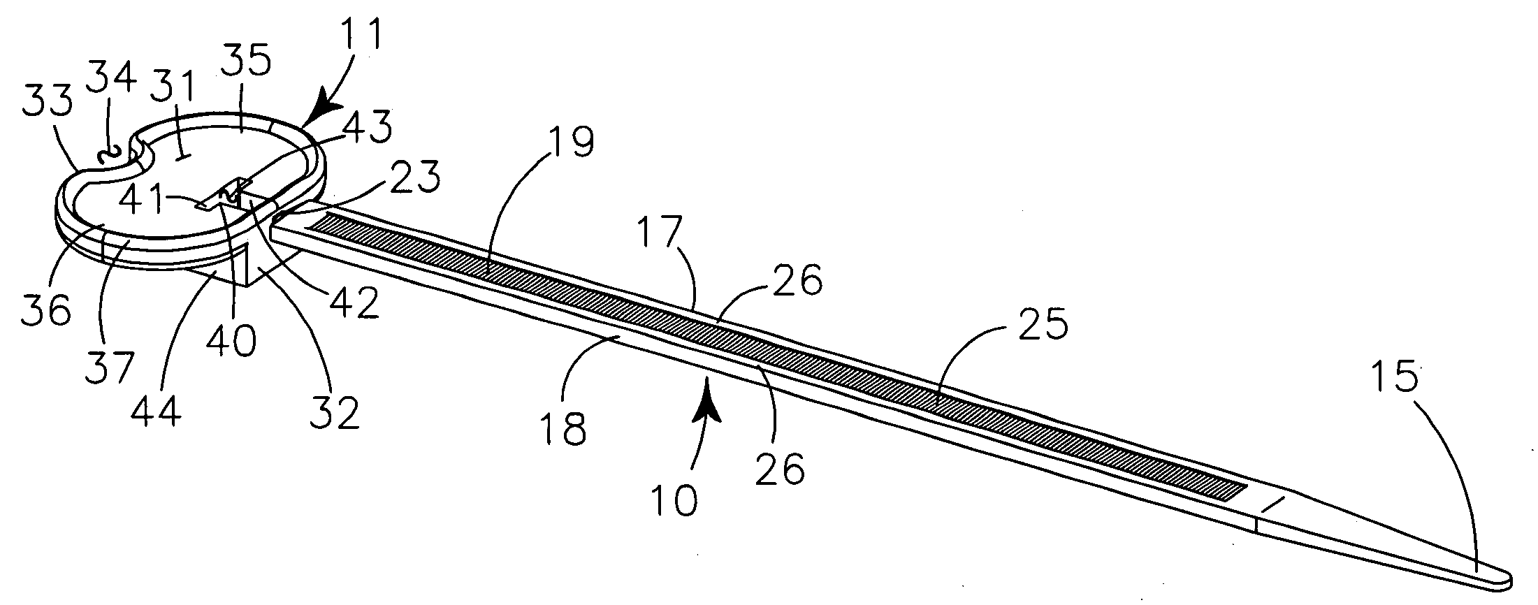
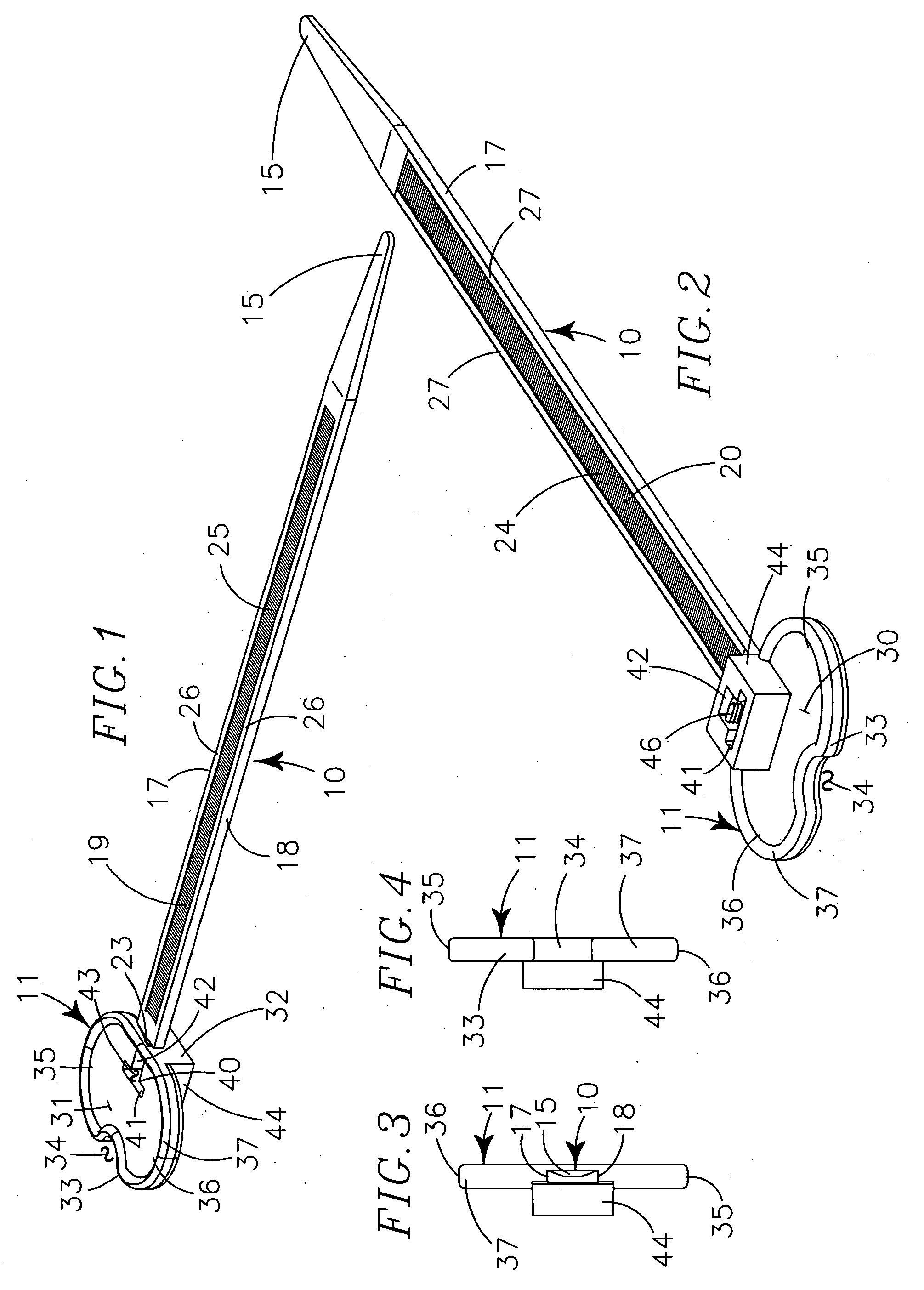
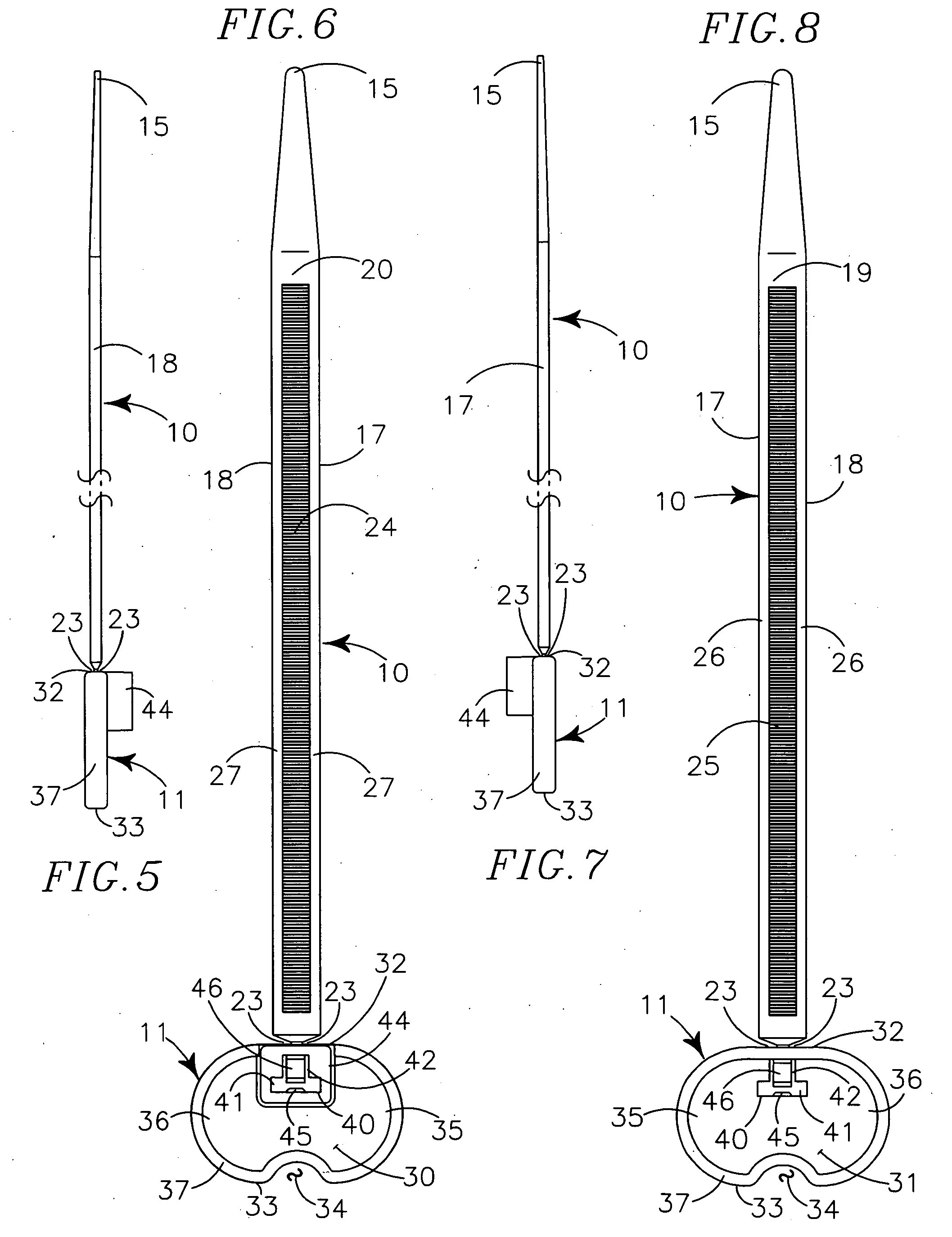
[0020]A twist-off tamper-proof fastener having an elongate flexible strap defining a plurality of parallel adjacent transverse teeth in opposing planar surfaces. First end portion of elongate strap is tapered to a rounded tip for insertion through a “T” slot defined in a head portion carried at opposing end of the elongate strap. A fixed tooth and plural angulated teeth carried by a flexing arm irremovably engage with the teeth defined in the elongate strap. The head portion is elliptic with opposing spaced apart rounded ends and opposing planar sides to facilitate grasping and twisting by a user, and for identifying indicia. A circumferentially extending notch is defined in the elongate strap immediately adjacent the head portion. Twisting the head portion focuses shearing forces at the circumferential notch breaking the cable tie and allowing removal without tools.
[0028]a further object to provide a twist off tamper-proof fastener having a peripheral frame around the “T” slot that prevents tampering with the arm.
[0039]a still further object to provide a twist off tamper-proof fastener that is of new and novel design, of rugged and durable nature, of simple and economic manufacture and one that is otherwise well suited to the uses and purposes for which it is intended.

Problems solved by technology

Once the elongate strap is inserted through the slot and the pawl has engaged with the parallel transverse grooves, the elongate strap cannot be withdrawn from the slot without breaking the pawl, breaking the elongate strap or otherwise physically destroying the cable tie.
Once the cable tie has been broken, it cannot be repaired or re-affixed.
The inability to remove a fastened cable tie without physically or functionally destroying the cable tie is both a desirable feature and a drawback.
Conversely, if the container or the cable tie have been broken, it can reasonably be assumed that the original contents of the container have been tampered with and are no longer in the condition and perhaps quantity, as they were when the cable tie was originally secured to the container.
By the same token, one of the drawbacks of cable ties is that they are difficult to break.
Cutting the cable tie with a wire cutter or knife poses a risk of unintentionally damaging the item being secured and requires use of a tool.
Breaking the cable tie by inserting an elongate rigid object, such as a screwdriver, through the looped elongate strap and twisting the object to break the cable tie is even more likely to damage the item secured by the cable tie.
Unfortunately, shearing forces such as those used to intentionally break known “tear away” cable ties may be inadvertently applied to the cable tie if the rectilinear tag is inadvertently caught between two surfaces that move relative to one another, such as a top and a bottom or adjacent sides of adjacent containers being transported in a vehicle.
Further, known “tear away” cable ties with rectilinear tags have sharp edges and corners, they are not aesthetically pleasing, they are difficult to package in bundles because the rectilinear tags “catch” on one another and they can be difficult to manufacturer.
When broken, the fact the cable tie has been broken is un-mistakenly identifiable.

Method used


Image

  • Twist off tamper-proof fastener
  • Twist off tamper-proof fastener
  • Twist off tamper-proof fastener

Examples


Embodiment Construction

[0052]A twist off tamper-proof fastener generally provides an elongate strap 10 having a head portion 11 defining “T” slot 40. The elongate strap 10 and head portion 11 are preferably formed of polypropylene, but may also be formed of nylon, polyethylene and other flexible resiliently deformable plastics.

[0053]The elongate strap 10 carries the head portion 11 at one end and is tapered to a rounded tip 15 at the opposing end portion to ease insertion through the “T” slot 40. The elongate strap 10 has a first side 19 and an opposing second side 20 defined by first elongate edge portion 17 and second elongate edge portion 18.

[0054]A plurality of parallel adjacent coarse teeth 25 are defined in the first side 19 and extend transversely partially across the first side 19 from a position spaced apart from the first elongate edge portion 17 to a position spaced apart from the second elongate edge portion 18, leaving border 26 adjacent the first elongate edge 17 and second elongate edge 18 ...


PUM


Abstract

A twist off tamper-proof fastener having an elongate flexible strap defining a plurality of parallel adjacent transverse teeth in opposing planar surfaces. First end portion of elongate strap is tapered to a rounded tip for insertion through a “T” slot defined in a dimensionally larger head portion carried at opposing end of the elongate strap. A fixed tooth and plural angulated teeth carried by a flexing arm irremovably engage with the teeth defined in the elongate strap. The head portion is elliptic with opposing spaced apart rounded ends and opposing planar sides to facilitate grasping and twisting by a user, and for identifying indicia. A circumferentially extending notch is defined in the elongate strap immediately adjacent the head portion. Twisting the head portion creates shearing forces that are focused at the circumferential notch breaking the fastener and allowing removal without tools.

Description

RELATED APPLICATIONS[0001]There are no other patent applications related hereto heretofore filed in the United States of America or in any other country.BACKGROUND OF INVENTION[0002]1. Field of Invention[0003]This invention relates to clasps and closures and more particularly to single use fasteners having a head portion defining a slot at one end of an elongate strap that loops over and irremovably engages in the slot.[0004]2. Background and Description of Prior Art[0005]Fasteners of the instant type are commonly referred to as “cable ties” and are well-known for fastening items together such as container latches, bundles of wire and groupings of flexible tubular members. Typically the fastener is threaded through adjacent aligned holes defined in portions of a container that move distally from one another when the container is opened, or the fastener is extended circumferentially around the bundle of wires / groupings of hose to secure the wires / hoses in proximity to one another.[00...

Claims


Application Information

Patent Timeline
IPC IPC(8): B65D63/10
CPCB65D63/1072Y10T24/1498Y10T24/14Y10T292/507
Inventor WILLIAMS, MARK KENTWILLIAMS, DAVID JOEFRY, KENNETH GARNET
Owner F BALDWYKER
Learn More