
High-efficiency transmitter with load impedance control

a transmitter and load impedance technology, applied in the field of communication transmitters, can solve the problems of limited utility, substantial efficiency reduction, and effective approach, and achieve the effect of reducing the effective load impedance zout, and reducing the effective load impedan

Active Publication Date: 2010-03-18
APPLE INC
View PDF8 Cites 17 Cited by
  • Summary
  • Abstract
  • Description
  • Claims
  • Application Information

AI Technical Summary

Benefits of technology

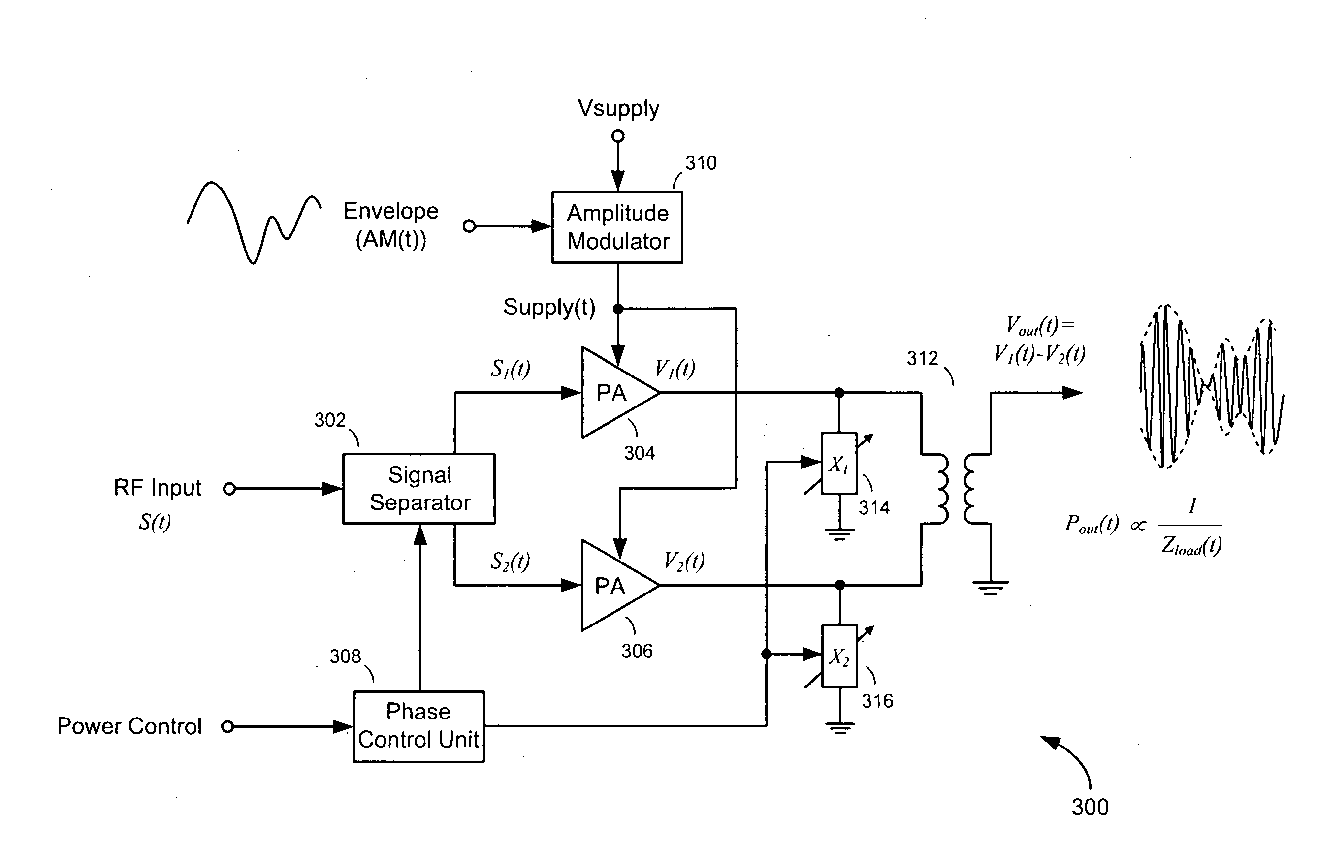
[0016]The power control signal controls the first and second phase angles of the first and second constant-envelope RF component signals independent of the amplitude of the RF input signal, the amplitude of the amplitude-modulated power supply signal, the amplitude of the first and second amplitude-modulated RF signals, or the amplitude of the modulated RF output signal. The power control signal also varies slowly over time compared to amplitude variations in these signals. According to one embodiment of the invention, the reactive component of the effective load impedance Zout is reduced by coupling variable shunt reactances at the RF outputs of the first and second nonlinear PAs. The reactances of the variable shunt reactances are adaptively controlled by the phase controller in response to the power control signal. Because the reactances of the variable shunt reactances are controlled by the slowly-varying power control signal, the effective load impedance Zout can be optimized for a wide range of average output powers Pout. Further, nonlinear effects caused by the variable shunt reactances' inability or difficulty to respond quickly enough to rapid amplitude changes in the input signal envelope are avoided.
[0017]By controlling the effective load impedance Zout and average output power Pout based on the power control signal, the transmitter is able to operate over a wide dynamic range without requiring a sacrifice in efficiency at low average output powers Pout. There is no need to scale down the AM signal AM(t) or operate the nonlinear PAs in product mode in order to provide and control low average output powers Pout. The first and second nonlinear PAs can be operated in compressed mode where they are highly efficient, even when the transmitter is configured to transmit at low average output powers Pout.

Problems solved by technology

However, this approach is effective only if the signal applied to the PA has a constant envelope.
Unfortunately, these requirements result in a substantial reduction in efficiency.
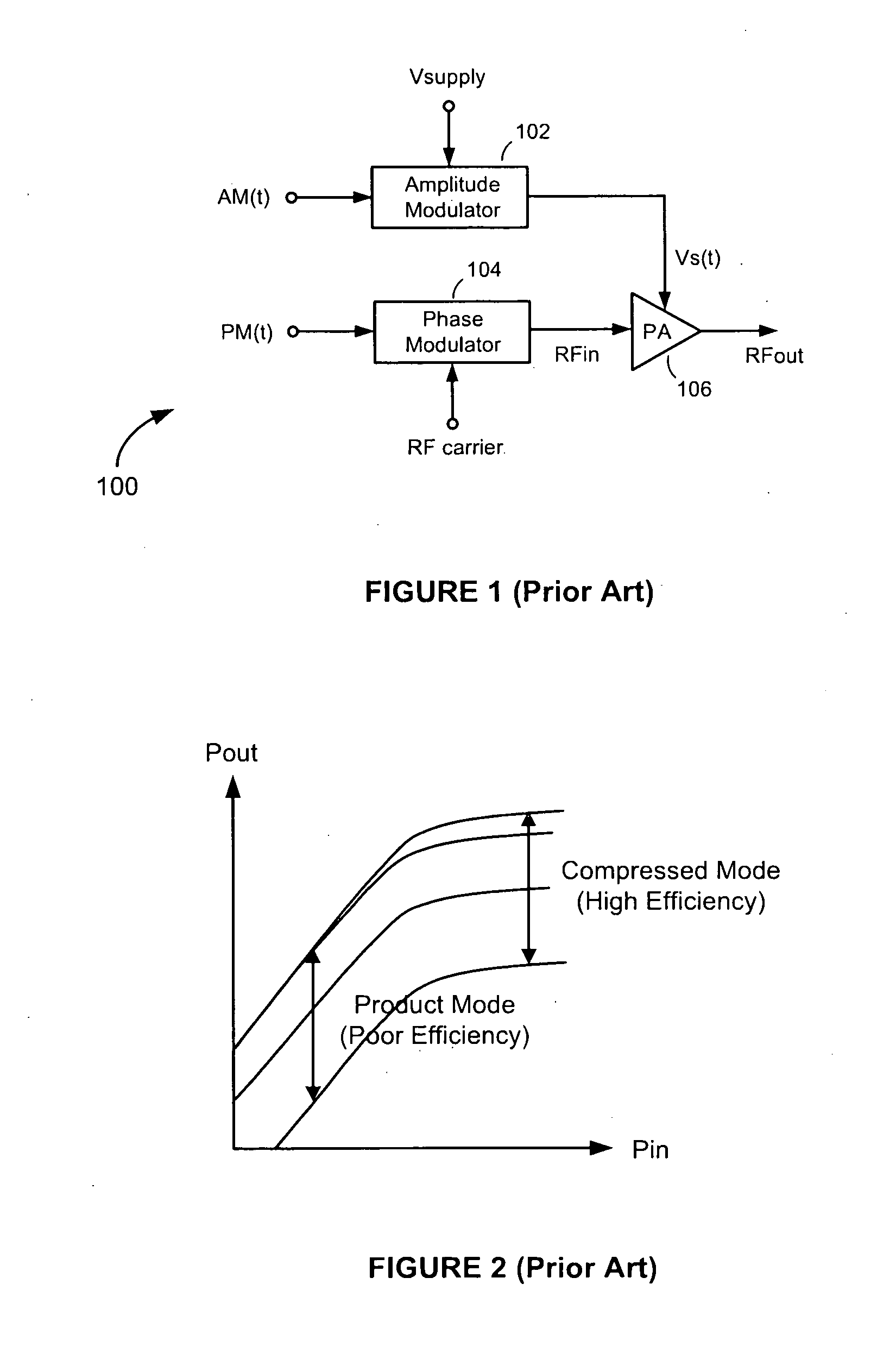
Although the polar transmitter 100 does achieve a significantly higher efficiency compared to linear-amplifier-based transmitters, its utility can be limited in applications that require a wide range of controllable output powers.
The difficulty the polar transmitter 100 has in controlling average output Pout over a wide dynamic range is due in part to the difficulty in designing an amplitude modulator 102 that can control the amplitude of the amplitude-modulated power supply signal Vs(t) over a wide dynamic range.
While some types of amplitude modulator circuits are highly efficient, most do not succeed in the ability of the amplitude modulator 102 to control the amplitude of the amplitude-modulated power supply signal Vs(t) over the range of amplitudes necessary to control the average output power Pout over the wide dynamic ranges required by standards.
Controllability is particularly difficult when the average output power Pout to be controlled is low, such as at −50 dBm in the W-CDMA standard.
The dynamic range limitation of the PA 106 results in spectral regrowth outside the desired or allocated transmission band.
At low average output powers Pout, where distortion is most severe, the degree of spectral regrowth can be significant enough that compliance with standards is not possible.
However, this is accomplished at the expense of efficiency, since, as illustrated in FIG. 2, the PA 106 operates less efficiently in product mode than it does when operating in compressed mode.

Method used


Image

  • High-efficiency transmitter with load impedance control
  • High-efficiency transmitter with load impedance control
  • High-efficiency transmitter with load impedance control

Examples


Embodiment Construction

[0027]Referring to FIG. 3, there is shown a transmitter 300, according to an embodiment of the present invention. The transmitter 300 comprises a signal separator 302, first and second power amplifiers (PAs) 304 and 306, a phase control unit 308, an amplitude modulator 310, a transformer 312, and first and second variable shunt reactances 314 and 316.

[0028]The signal separator 302 is configured to receive a radio frequency (RF) input signal S(t) and generate therefrom first and second constant-envelope RF component signals S1(t) and S2(t) having opposite (i.e., first and second) phase angles +φ(t) and −φ(t) relative to the phase of the RF input signal S(t). The vector sum of the first and second constant-envelope RF component signals S1(t) and S2(t) relates to the RF input signal S(t) as shown in the phasor diagram in FIG. 4. In the description of the exemplary embodiment that follows, it is assumed that the RF input signal S(t) is a phase-modulated RF signal having phase modulation...


PUM


Abstract

A transmitter generates first and second constant-envelope radio frequency (RF) component signals having first and second phase angles. The first and second phases are controlled by a phase controller. First and second nonlinear power amplifiers (PAs) are modulated by an amplitude-modulated power supply signal as the first and second constant-envelope RF component signals are amplified. The phase controller controls the first and second phases of the first and second constant-envelope RF component signals, in response to a power control signal, and, in so doing, controls an effective load impedance seen at the outputs of the first and second nonlinear PAs. By controlling the effective load impedance in response to a power control signal, rather than in response to rapid amplitude variations in an input signal envelope, the output power of the transmitter is efficiently controlled over a wide dynamic range even at low output powers.

Description

FIELD OF THE INVENTION[0001]The present invention relates to communications transmitters. More specifically, the present invention relates to methods and apparatus for generating and transmitting communications signals at high efficiencies and over wide dynamic ranges of controlled power.BACKGROUND OF THE INVENTION[0002]Achieving high power efficiency is one of the most important goals in the design of the transmitter of a battery-powered wireless communications device, such as a cellular handset. The dominant consumer of power in the transmitter is usually the transmitter's power amplifier (PA). For this reason, efforts to improve the efficiency of the transmitter have focused in large part on ways to improve the efficiency of the PA.[0003]The efficiency of a PA can be increased by operating the PA close to, or in, saturation. However, this approach is effective only if the signal applied to the PA has a constant envelope. Many existing or soon-to-be deployed technologies, such as ...

Claims


Application Information

Patent Timeline
IPC IPC(8): H04B1/04
CPCH03F1/0222H03F3/19H03F3/211H03F3/24H04B1/0475H03F2200/541H03G3/3042H04B1/0458H03F2200/451
Inventor TAKINAMI, KOJILIANG, PAUL CHENG-PO
Owner APPLE INC
Learn More