
Vessel for transporting wind turbines and methods thereof

a wind turbine and wind power technology, applied in special purpose vessels, passenger handling apparatuses, runways, etc., can solve the problems of limited deck space of derrick barges, limited deck space and valuable effects

Inactive Publication Date: 2010-03-18
SPRING CAPITAL RESOURCES
View PDF50 Cites 37 Cited by
  • Summary
  • Abstract
  • Description
  • Claims
  • Application Information

AI Technical Summary

Benefits of technology

[0018]Another method of erecting a wind turbine offshore may include lifting a wind-turbine column from a wind-turbine foundation affixed to the deck of a vessel using a crane disposed on the vessel, wherein the crane includes a crane support having at least two vertical members with each vertical member having a first and second end, the first end of the first vertical member is affixed to a first track, the first end of the second vertical member is affixed to a second track, the first and second tracks are affixed to a deck of the vessel, the second end of the first vertical member is affixed to a first side of a platform, the second end of the second v

Problems solved by technology

Due to the limited storage capacity of the derrick barges, multiple sailings are generally necessary to complete erection of a wind farm.
Thus, the derrick barge's ability to erect an offshore wind turbine is limited.
Moreover, the available deck space of the derrick barge is limited.
These drilling rigs can withstand harsh weather conditions and may be deployed for long periods of time.
Due to the nature of the work, deck space is limited and valuable.
These smaller vessels generally cannot withstand harsh weather conditions and are typically designed to move, under their own power and without the need for a tug boat, out of the way of bad weather.
Accordingly, a lift boat is limited in its size and ability, and cannot function as a jack-up rig.

Method used


Image

  • Vessel for transporting wind turbines and methods thereof
  • Vessel for transporting wind turbines and methods thereof
  • Vessel for transporting wind turbines and methods thereof

Examples


Embodiment Construction

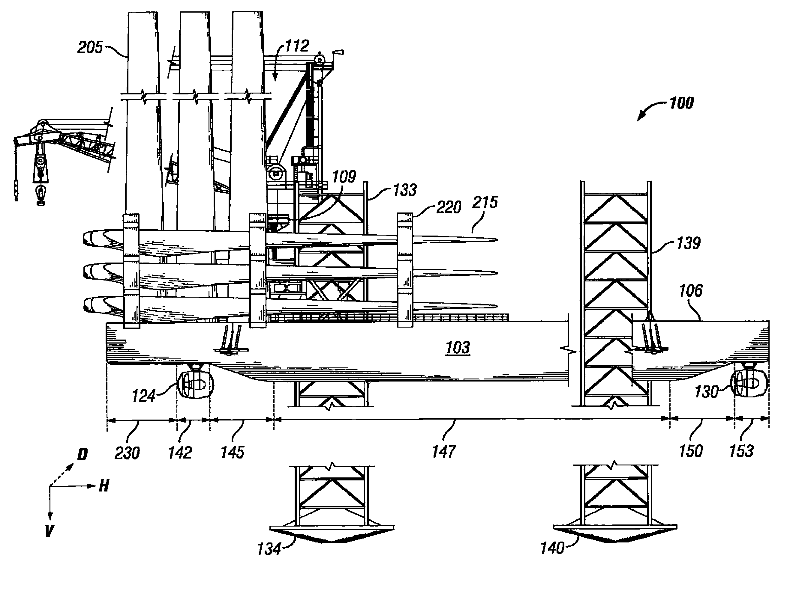
[0028]In an embodiment, the terms “horizontal axis” or “horizontal” mean a direction along the length of a vessel from the transom of the vessel to the bow of the vessel.

[0029]In an embodiment, the terms “vertical axis” or “vertical” mean a direction along the width of a vessel from the port of the vessel to the starboard of the vessel.

[0030]In an embodiment, the terms “depth axis”, “depth”, or “deep” mean a direction along the depth of a vessel from the bottom of the vessel to the top of the vessel.

[0031]In an embodiment, the term “still water line” means the level of the water without wind or other disturbances which artificially impacts the level of the water, such as the wake from another vessel.

[0032]In an embodiment, the term “air gap” means the distance from the lowest portion of the hull of a vessel to the still water line.

[0033]In an embodiment, the term “self propelled” or “self propelled vessel” means a vessel that is capable of navigating open waters without the assistan...


PUM


Abstract

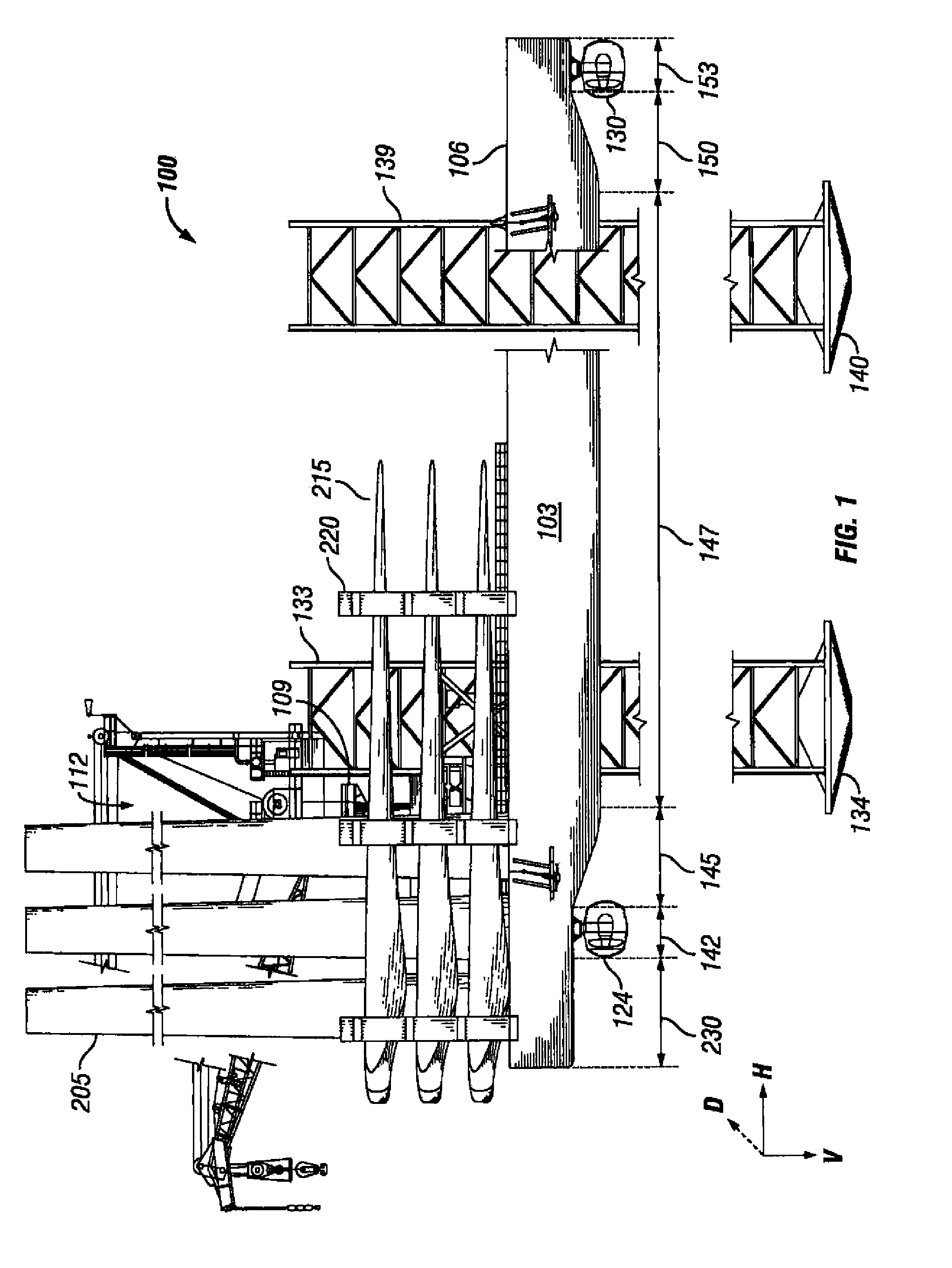
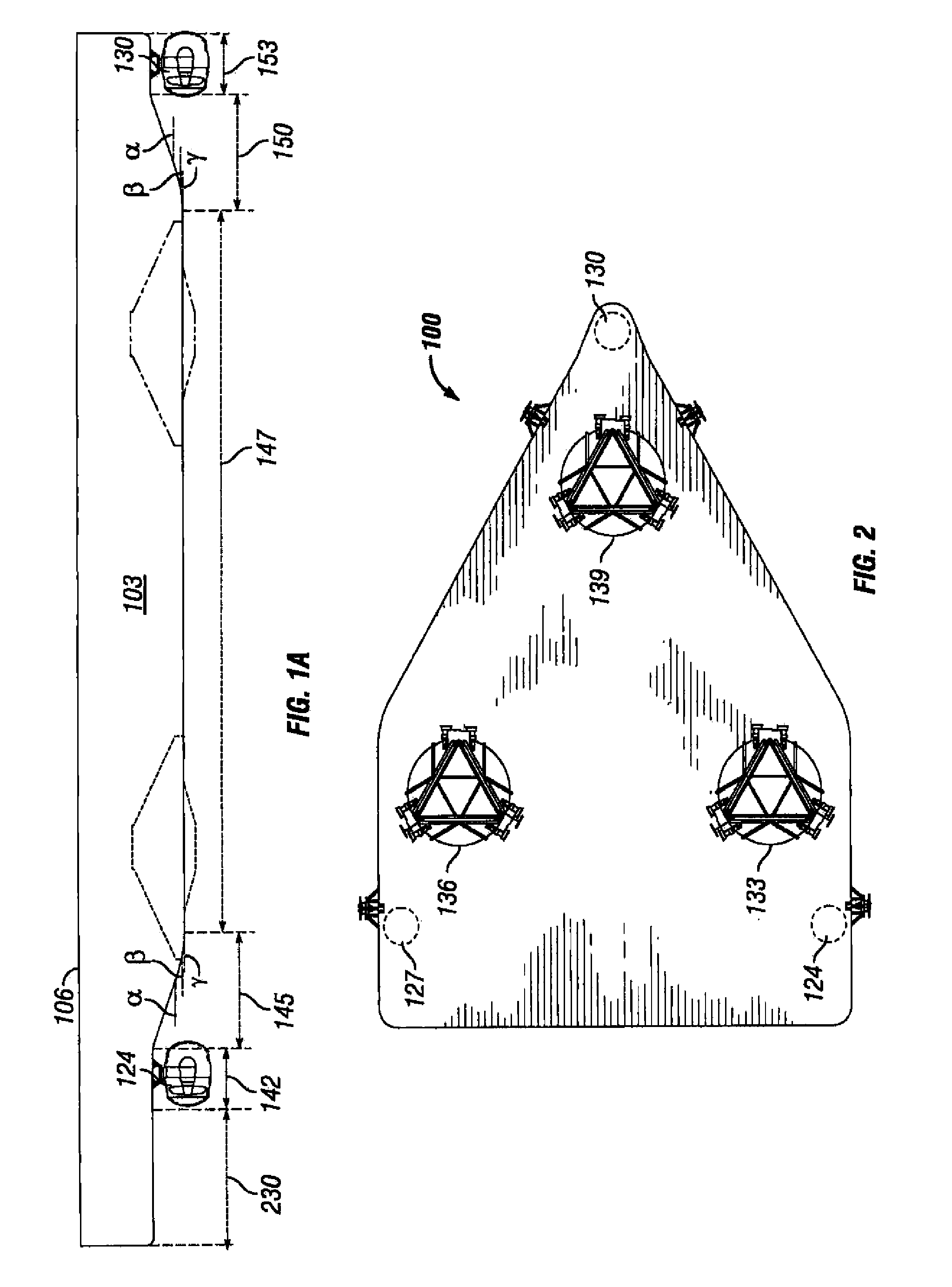
A vessel having the capability of storing, transporting, and installing between one and ten wind turbines is provided. Such a vessel includes a hull having a hull periphery. The vessel further includes at least two rear jack-up legs, and at least one forward jack-up leg, movably attached to the hull, as well as a jacking mechanism connected to each of the jack-up legs for elevating and lowering each jack-up leg relative to the hull between elevated and lowered positions. The vessel also includes at least two rear azimuthing thrusters affixed to a lower side of the transom; and at least one front azimuthing thruster affixed to a lower side of the bow. The vessel further includes at least four, preferably at least six, wind-turbine-column foundations, and at least two wind-turbine-blade brackets individually mounted to the side of the transport vessel.

Description

CROSS-REFERENCE TO RELATED APPLICATIONS[0001]This application is a continuation in part of U.S. application Ser. No. 12 / 079,309 filed Mar. 26, 2008, which claims the benefit of U.S. Provisional Application No. 60 / 920,965 filed Mar. 30, 2007 and U.S. Provisional Application No. 61 / 030,815 filed Feb. 22, 2008, this application also claims the benefit and priority of U.S. Provisional Application No. 61 / 094,269 filed Sep. 4, 2008.FIELD OF THE INVENTION[0002]This invention relates to modified vessels capable of transporting a segmented wind-turbine to an offshore location, and methods of transporting, storing, and erecting the offshore wind turbine.DESCRIPTION OF RELATED ART[0003]Wind-turbine generated electricity is an alternative to oil and gas energy sources. For a number of reasons, including maintenance efficiency, permitting, and general organization, it is often desirable to erect a plurality of wind turbines within close proximity to one another. Such a group is called a wind far...

Claims


Application Information

Patent Timeline
IPC IPC(8): E02B17/08
CPCB63B27/02B63B27/30B63B35/00B63B35/003B66C7/08B66C23/52Y02E10/727E02B2017/006E02B2017/0082E02B2017/0091F03D1/001F03D1/005F05B2240/95E02B17/021F03D13/10F03D13/40B63B27/19Y02E10/72
Inventor BROWN, MICHAEL D.ALTMAN, RICHARD A.LECOMPTE, CHRISTOPHER C.
Owner SPRING CAPITAL RESOURCES
Learn More