
Method and Apparatus of Load Detection for a Planar Wireless Power System

a power system and wireless technology, applied in the direction of voltage/current isolation, base element modification, instruments, etc., can solve the problems of reducing system efficiency, communication link adds cost and size to the system, restricts the portability of mobile electronic devices, etc., and achieves low cost.

Active Publication Date: 2010-03-18
UNIV OF FLORIDA RES FOUNDATION INC
View PDF5 Cites 204 Cited by
  • Summary
  • Abstract
  • Description
  • Claims
  • Application Information

AI Technical Summary

Benefits of technology

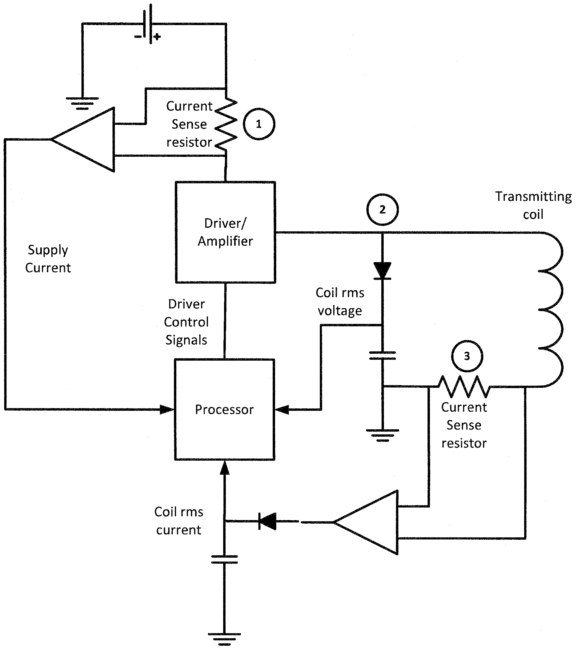
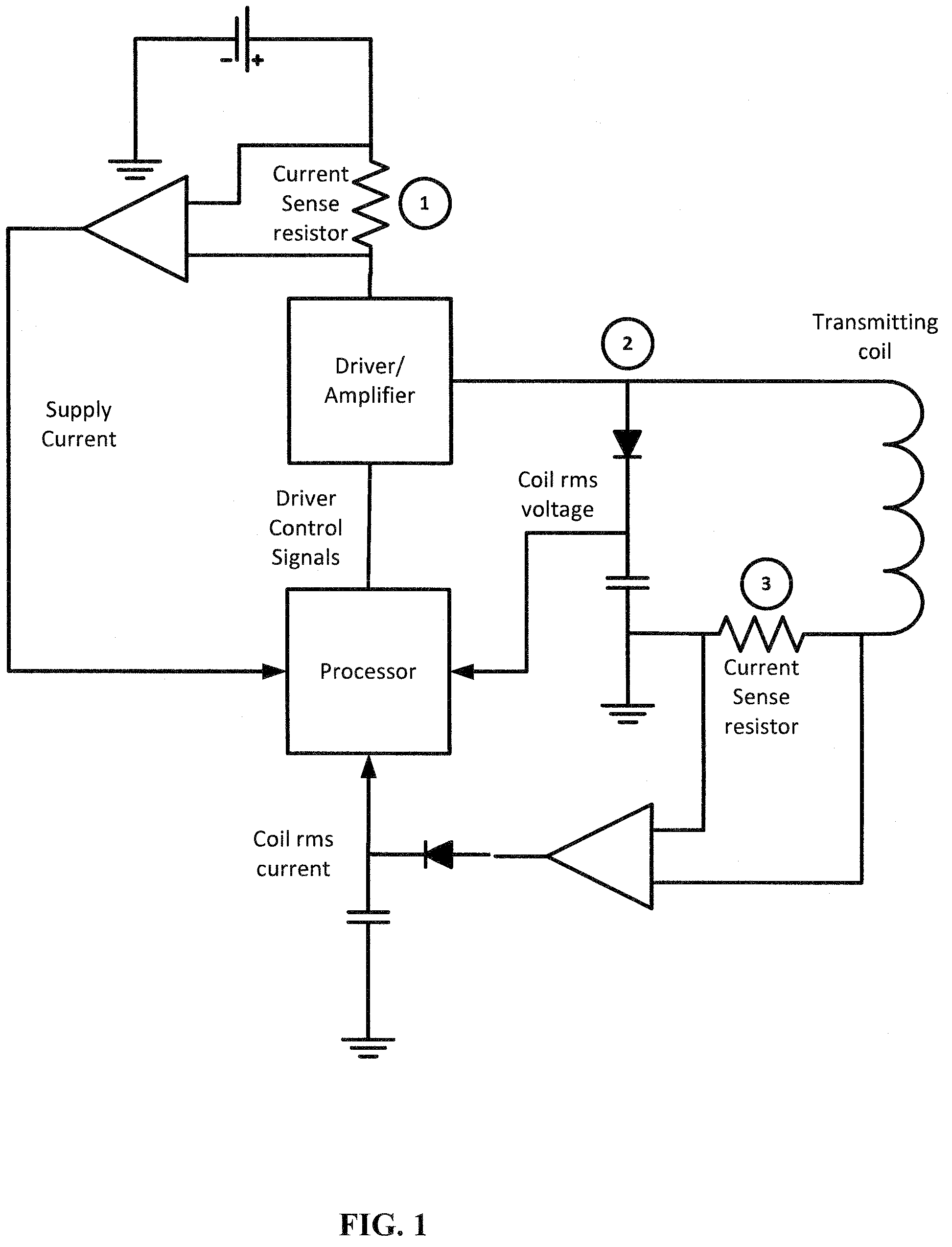
[0006]Embodiments of the subject invention relate to a method and apparatus for determining information regarding a load in a planar wireless power transfer system by extracting system operating parameters from one or more test points in the transmitter circuit. As shown in FIG. 1, a specific embodiment showing three test points in the transmitter circuit from which operating parameters can be extracted. The transmitter circuit is designed to produce a magnetic field, by driving the transmitter coil, which inductively couples to a receiver coil such that power is provided to a receiver. By extracting operating parameters from the transmitter circuit, the receiver does not need to incorporate sophisticated signal processing and can be manufactured with low cost.

Problems solved by technology

The cables that once restricted electronic devices are gradually being rendered unnecessary by wireless communication technology, and as the circuits that constitute the electronic devices shrink, only the power cords and batteries continue to restrict the portability of mobile electronic devices.
However, a communication link adds cost and size to the system, which is not desirable for a compact receiving unit to be integrated inside a portable device.
However, such systems are typically complicated and consume large amounts of power which reduce system efficiency and increase system cost.

Method used


Image

  • Method and Apparatus of Load Detection for a Planar Wireless Power System
  • Method and Apparatus of Load Detection for a Planar Wireless Power System
  • Method and Apparatus of Load Detection for a Planar Wireless Power System

Examples


Embodiment Construction

[0015]Embodiments of the subject invention relate to a method and apparatus for determining information regarding a load in a planar wireless transfer system by extracting system operating parameters from one or more test points in the transmitter circuit. As shown in FIG. 1, a specific embodiment showing three test points in the transmitter circuit from which operating parameters can be extracted. The transmitter circuit is designed to produce a magnetic field, by driving the transmitter coil, which inductively couples to a receiver coil such that power is provided to a receiver. By extracting operating parameters from the transmitter circuit, the receiver does not need to incorporate sophisticated signal processing and can be manufactured with low cost.

[0016]Test point 1 in FIG. 1 shows where the supply current of the system can be measured. The embodiment shown in FIG. 1 is to use a current sense resistor and a differential amplifier located on the high side of the power supply t...


PUM


Abstract

Embodiments of the subject invention relate to a method and apparatus for determining information regarding a load in a planar wireless power transfer system by extracting system operating parameters from one or more test points in the transmitter circuit. As shown in FIG. 1, a specific embodiment showing three test points in the transmitter circuit from which operating parameters can be extracted. The transmitter circuit is designed to produce a magnetic field, by driving the transmitter coil, which inductively couples to a receiver coil such that power is provided to a receiver. By extracting operating parameters from the transmitter circuit, the receiver does not need to incorporate sophisticated signal processing and can be manufactured with low cost.

Description

BACKGROUND OF INVENTION[0001]Portable electronic devices such as laptop computers, LCD digital photo frames, mobile phones, and mp3 players require power to operate. Often, these devices use rechargeable batteries to provide power. The batteries are typically recharged by plugging a charger into the portable device or by removing the battery from the portable device and separately recharging the battery using a wired charger.[0002]The cables that once restricted electronic devices are gradually being rendered unnecessary by wireless communication technology, and as the circuits that constitute the electronic devices shrink, only the power cords and batteries continue to restrict the portability of mobile electronic devices.[0003]Current trends are leading towards going completely wireless. This means that portable devices can remain portable and can avoid having to ‘plug-in’ for power charging. Electro-magnetic inductive charging uses a coil to create an electromagnetic field across...

Claims


Application Information

Patent Timeline
Patent Type & Authority Applications(United States)
IPC IPC(8): G01R19/00
CPCH02J5/005H02J50/80H02J7/0048H02J50/40H02J50/10
Inventor LIN, JENSHANLOW, ZHEN NING
Owner UNIV OF FLORIDA RES FOUNDATION INC
Learn More