
Batten/joist support

a joist support and batten technology, applied in the field of improved, can solve the problems of joist not fitting securely between the two walls of the mounting, the joist is sized to suit and the mounting is not suitable for the width of the jois

Inactive Publication Date: 2010-03-11
LEE IN OK
View PDF46 Cites 25 Cited by
  • Summary
  • Abstract
  • Description
  • Claims
  • Application Information

AI Technical Summary

Problems solved by technology

However, there are a number of problems in using such mountings.
The first problem is that the mounting is sized to suit the width of the joist.
Therefore if the joist is oversized in width, the joist will not fit securely between the two walls of the mounting.
Secondly, even if the width of the joist does match the gap defined between the walls of the mounting, the joists tend to be quite long and are supported by numerous pedestals each carrying their own support.
The supports have to be correctly aligned in order to receive the joist, and it is very time consuming to align the supports sufficiently to fit the joists.

Method used


Image

  • Batten/joist support
  • Batten/joist support
  • Batten/joist support

Examples


Embodiment Construction

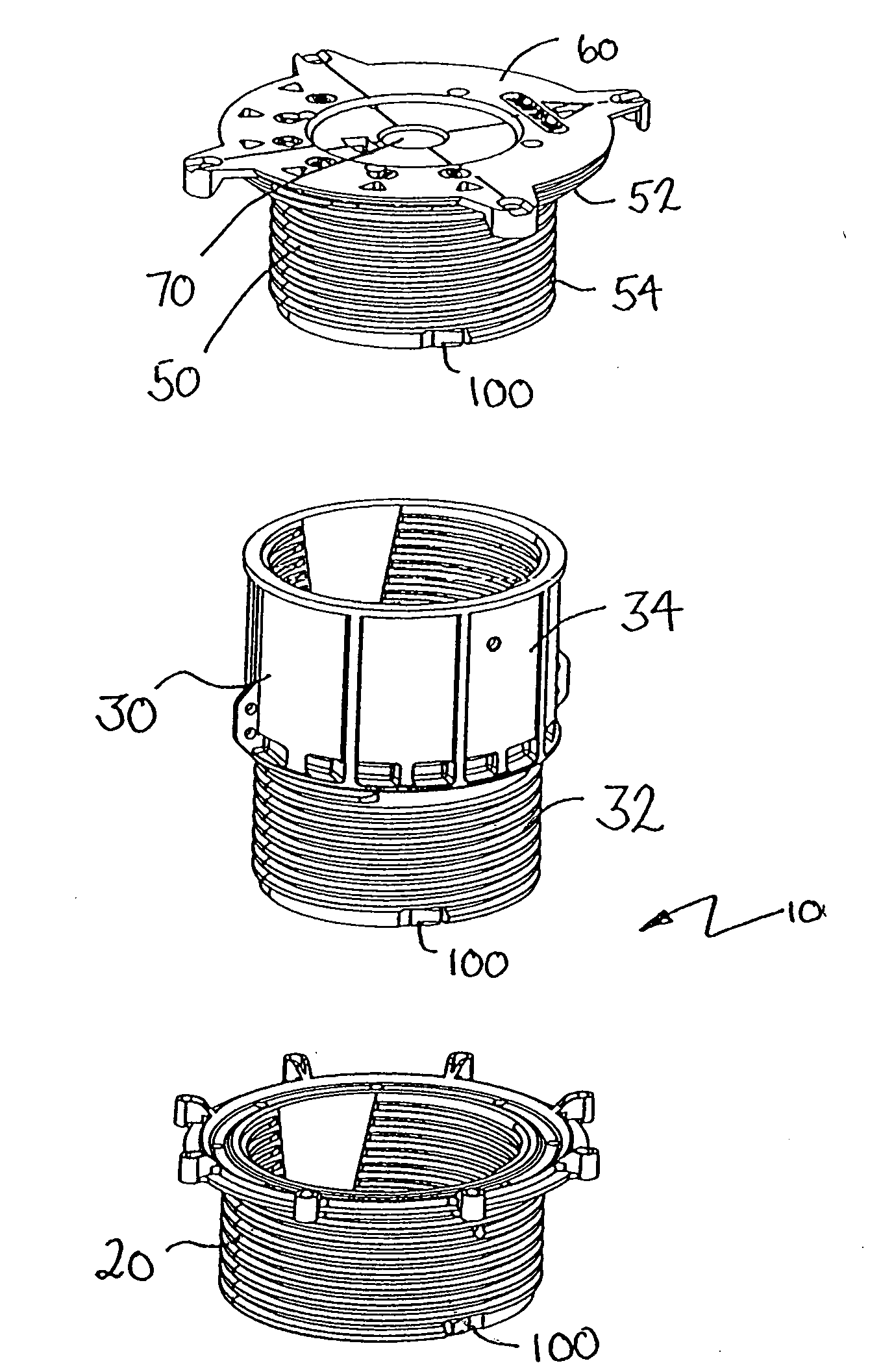
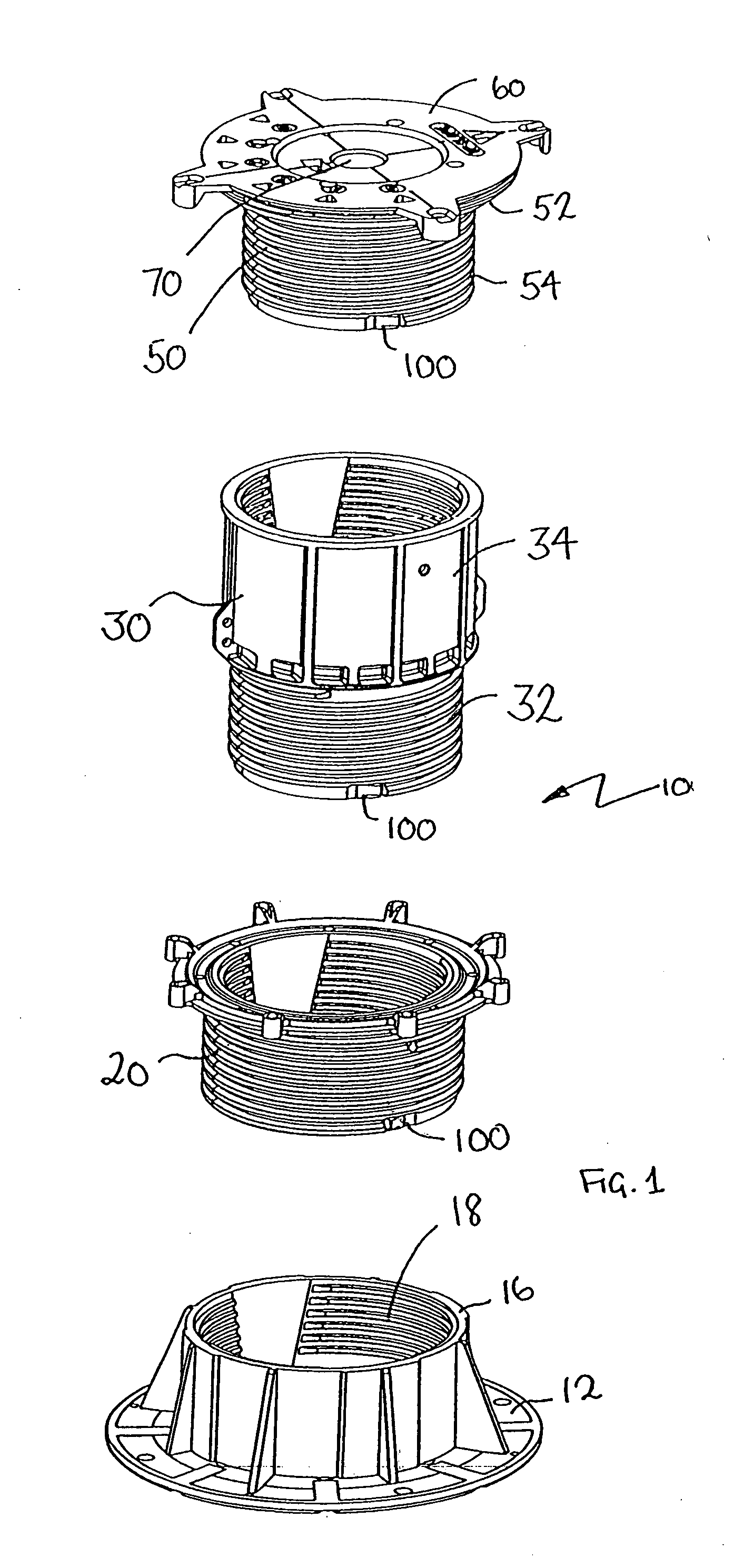
[0029]Referring to the drawings, to provide a context for the invention, FIG. 1 shows a height adjustable pedestal 10 incorporating slope adjustment comprising a number of components. As shown, the height adjustable pedestal comprises a base element 12, having a circular planar base plate 14 defining a plane on which the pedestal stands in use, and an annular cylindrical portion 16 extending upwards from the base. The annular portion 16 is internally (female) threaded defining six internal threads 18. Spaced above the base 12 is a connector 20 which has an annular cross section and is internally and externally (male) threaded. The externally threaded portion locates in the base 16. Located above the connector 20 is an extender 30 which has a generally annular cross section comprising a lower portion 32 which is externally threaded and configured to locate inside the connector 20 and an upper, larger diameter portion 34 which is internally threaded. A head portion 50 includes an uppe...


PUM


Abstract

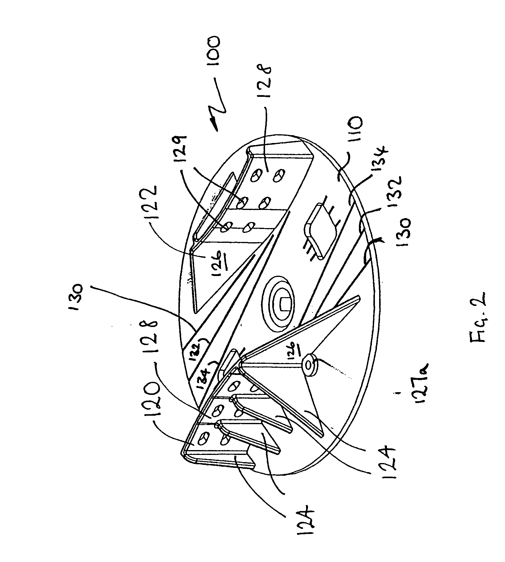
A support means (100) for engaging a batten, joist or the like (200), includes a circular rotatable plate (110). The plate has depending legs (112) for engaging the support means with a support structure such as a pedestal jack or the like, in a manner which allows the support means to be rotated about a vertical axis passing through the centre (111) of the plate. The support means (100) further includes two opposed upstanding walls (120, 122) defining a gap for receiving the batten, joist or the like. The walls are disposed either side of the axis and extend from a centremost position closest to the axis (111) to a distal end farthest from the axis. The walls are at least partly convex, and the gap between the walls measured in a direction perpendicular to tangents to the walls decreases from the centremost part of the wall to the distal end of the wall, so that for a joist batten or the like having a predetermined width and positioned between the walls (120, 122), rotation of the support means about the axis in one sense causes the walls (120, 122) to tend to abut edges of the joist and in the opposite sense causes the walls (120, 122) to tend to move away from the edges of the joist. The walls define apertures (129) for fastening the walls to the joist with nails, screws or the like.

Description

FIELD OF THE INVENTION[0001]This invention relates to an improved batten / joist support, particularly, but not exclusively, for raised floors.BACKGROUND OF THE INVENTION[0002]It is known to provide floors raised above a sub-floor comprising boards assembled on a framework comprising joists or battens, with the boards connected to the joists by means of coupling members. Typically, the sub-floors will be concrete. The boards are often made from wood or wood based composite materials, although other materials may be used. The joists are often mounted on height and slope adjustable pedestal supports, (also known as pedestal jacks) particularly where the sub-floor is sloping, to ensure that the raised floor is substantially horizontal. An example of an adjustable pedestal jack is shown in international patent application No PCT / AU2006 / 001613.[0003]When such raised floors are mounted on pedestal jacks, a mounting component is typically provided for mounting the joist the top of such pedes...

Claims


Application Information

Patent Timeline
Patent Type & Authority Applications(United States)
IPC IPC(8): E04F15/024E04B1/38
CPCE04D12/006E04F15/02482
Inventor GREAVES, HENRY
Owner LEE IN OK
Learn More