Printing apparatus

Inactive Publication Date: 2010-03-04
SEIKO EPSON CORP
View PDF2 Cites 20 Cited by
  • Summary
  • Abstract
  • Description
  • Claims
  • Application Information

AI Technical Summary

Benefits of technology

[0007]An advantage of some aspects of the invention is to suppress an increase in cost of a printing apparatus and to efficiently print a plurality of ink layers.
[0010]In the printing apparatus having the configuration, a specific gloss agent instead of the specific color ink can be ejected from the end-portion specific color nozzle column disposed to at least one end portion in the alignment direction of the nozzle columns. Since the end-portion specific color nozzle column is disposed at the end portion in the alignment direction, the specific gloss agent can be ejected before any one of the three primary color inks and the specific color ink or after any one thereof according to the direction of the relative movement of the print head with respect to the printing medium. In other words, the specific glossy layer and the image layer can be superposedly printed on the printing medium in the order of the specific glossy layer and the image layer or in the order of the image layer and the specific glossy layer. In addition, since specific gloss agent is ejected by using the specific color nozzle column, the print head needs not to have any nozzle column dedicated to the specific gloss agent, so that it is possible to implement an economical printing apparatus.
[0014]Since the printing apparatus having the configuration receives signals from the connected container to receive the kinds of the available inks, that is, to receive the kinds of the inks contained in the connected container, the printing apparatus can be easily manipulated.
[0018]Since the printing apparatus having the configuration can be adapted to a printing apparatus using light inks, the printing apparatus can be used with high general versatility.

Problems solved by technology

Therefore, there is a problem in that cost for the printing apparatus is increased.
Particularly, the printing apparatus is relatively expensive for a user who does not frequently use the metallic color printing.
The problem is not limited to the metallic color printing, but it commonly occurs in cases where an image layer representing an image and another layer are superposedly printed on the printing medium.

Method used


Image

  • Printing apparatus
  • Printing apparatus
  • Printing apparatus

Examples


modified example 1

E-1. MODIFIED EXAMPLE 1

[0063]In the embodiment, a metallic ink layer MR and a color ink layer CR are formed on an opaque printing medium P1 in this order, and metallic color printing is performed. However, the order of forming the ink layers may be reversed. For example, as shown in FIG. 7B, in a case where printing is performed on a transparent printing medium P2, the color ink layer CR and the metallic ink layer MR may be formed on the printing medium P2 in this order. As a result, when a printed material is observed in the direction from printing medium P2 to the metallic ink layer MR, the metallic color of the printed material can be observed.

[0064]In this case, since the order of forming the metallic ink layer MR and the color ink layer CR may be reversed with respect to the order of the example, the metallic ink S may be designed to be ejected from the nozzle column that is disposed at the rear end portion in the scan direction in which the ink ejecting is performed among the ...

modified example 2

E-2. MODIFIED EXAMPLE 2

[0065]In the embodiment and Modified Example 1, the one-directional printing is exemplified as the metallic color printing. However, the printer 200 may be configured for bi-directional printing. More specifically, for example, the ink change from light inks corresponding to the nozzle columns 256 and 257 that are disposed at the two end portions in the alignment direction of the nozzle columns of the print head 250 to the metallic inks S may be performed.

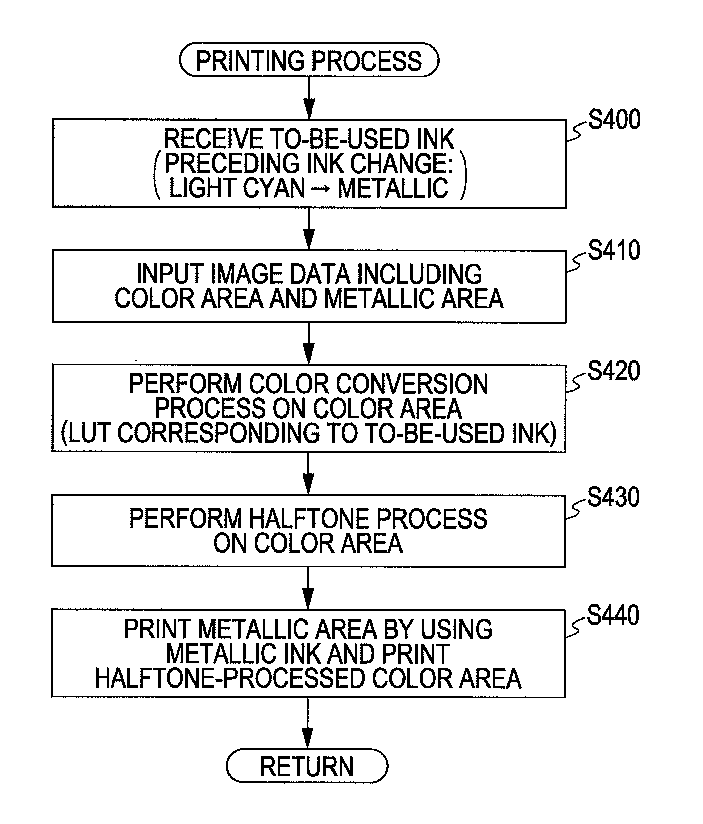
[0066]In this case, since the bi-directional printing is performed, the Step 430 shown in FIG. 5 can be replaced with, for example, a process shown in FIG. 8. More specifically, after a halftone process, the computer 100 determines whether or not a raster of a to-be-printed object includes a metallic area (Step S431). As the result of determination, if the metallic area is not included (Step S431: NO), only the nozzle columns 252 to 255 ejecting the color inks among the nozzle columns 252 to 257 provided to t...

modified example 3

E-3. MODIFIED EXAMPLE 3

[0072]FIG. 10 shows details of a print head 250b according to Modified Example 3. The print head 250b is different from the print head 250 shown in FIG. 6A in terms of the alignment of nozzle columns. More specifically, the example is different from the embodiment in that the nozzle column 257b and 255b corresponding to the specific color inks are disposed between the nozzle column 256b disposed at the front end portion in the scan direction of the print head and the nozzle columns 252b to 255b corresponding to the three primary colors.

[0073]In a case where the same metallic color printing as that of the embodiment is performed by using the print head 250b, if the to-be-printed image of the metallic area is to be formed with no use of the light magenta ink Lm and / or the black ink K or with almost no use thereof, and if the printing is performed by performing the conversion process in the Step S420, a time interval from the time when the metallic ink S is lande...


PUM


Abstract

Provided is a printing apparatus that superposedly forms an image layer representing an image and a specific glossy layer that is different from the image layer on a printing medium, including: a first connection unit that can be connected to a basic color ink container containing three primary color inks of which combination is used for performing color representation; a second connection unit that can be connected to a specific color ink container containing a specific color ink other than the three primary color inks; a reception unit that receives a kind of print available ink; a print head where nozzle columns in which a plurality of nozzles are aligned in a predetermined direction are arrayed in a direction intersecting an alignment direction of the nozzles in the nozzle columns, and at least one of specific color nozzle columns ejecting the specific color ink among the nozzle columns is disposed as an end-portion specific color nozzle column to at least one of end portions of the print head in the array direction of the nozzle columns; and a printing unit that performs printing by moving the print head relative to the printing medium and ejecting the three primary color inks and / or the specific color ink on the printing medium from the nozzle columns, wherein at least the connection unit that can supply the ink to the end-portion specific color nozzle column inside the second connection unit can be connected to a specific gloss agent container containing a specific gloss agent that is used to form the specific glossy layer instead of the specific color ink container, and wherein, when the specific gloss agent container is connected to the second connection unit and the reception unit receives the specific gloss agent as the available ink, the printing unit ejects the specific gloss agent from the end-portion specific color nozzle column to form the specific glossy layer.

Description

[0001]This application claims priority to Japanese Patent Application No. 2008-219055, filed Aug. 28, 2008, the entirety of which is incorporated by reference herein.BACKGROUND[0002]1. Technical Field[0003]The present invention relates to a printing technology for superposedly forming an image layer representing an image and a specific glossy layer that is different from the image layer on a printing medium.[0004]2. Related Art[0005]A method in which a primer coating layer is firstly formed on a printing medium and printing is performed on the primer coating layer is known (for example, Patent Document JP-T-2002-530229). The method can be adapted to various printing methods. For example, the method can be used to reproduce metallic colors having various tones. In order to reproduce the metallic color, for example, a metallic ink layer may be formed on a printing medium, and color inks are superposedly printed on the metallic ink layer.[0006]However, in order to perform the metallic ...

Claims


Application Information

Patent Timeline
IPC IPC(8): B41J2/21
CPCB41J2/2114B41J2/2107
Inventor SEISHIN, YOSHIDA
Owner SEIKO EPSON CORP
Why Eureka
Try Eureka