
Method for preventing signal collision in radio frequency identification system and radio frequency identification tag used thereof

a radio frequency identification system and radio frequency identification technology, applied in the field of wireless communication, can solve the problems of loss of signal transmission, inability of rfid reader to correctly read signals or even make incorrect determinations, and possible signal collision among tag signals read by rfid readers. to prevent signal collision

Inactive Publication Date: 2010-03-04
MITAC TECH CORP
View PDF5 Cites 10 Cited by
  • Summary
  • Abstract
  • Description
  • Claims
  • Application Information

AI Technical Summary

Benefits of technology

[0011]In one aspect of the present invention, a method is provided to prevent a signal collision in a RFID system. The RFID system includes at least one RFID reading device that comprises a microprocessor connected to a radio frequency transceiver module for receiving respective tag information from a plurality of RFID tags. The RFID tags each comprises a microprocessor connected to a memory unit and a radio frequency transceiver module; wherein the memory unit stores the respective tag information. The method comprising the following steps: (a) the RFID tag generates a random code; (b) the microprocessor of the RFID tag generates a time shift along a time axis based on the random code; (c) the RFID tag transmits a tag signal containing the tag information in accordance with the time shift; and (d) the RFID reading device receives the tag signal of the RFID tag.
[0012]In another aspect of the present invention, a method with the following steps is provided to prevent a signal collision in a RFID system. (a) The microprocessor of the RFID tag retrieves the tag information from the memory unit and basing on the tag information to generate a random code; (b) the RFID tag transmits a tag signal containing the tag information in accordance with the random code; and the RFID reading device receives the tag signal of the RFID tag.

Problems solved by technology

In applications where the RFID reader has to read multiple RFID tags simultaneously, signal collision may occur among the tag signals read by the RFID reader.
The former means an RFID reader simultaneously receive signals returned by multiple RFID tags, making it impossible for the RFID reader to correctly read the signals or even making incorrect determination, while the later is a situation where the same RFID tag receives different instruction from multiple RFID readers, leading to interference.
The occurrence of signal collision causes failure and loss of signal transmission and even incorrect interpretation of signal to make incorrect data, both being obstacles for identification operation.
Yet, a disadvantage that the total time required to read all the RFID tags are extended may be encountered.

Method used


Image

  • Method for preventing signal collision in radio frequency identification system and radio frequency identification tag used thereof
  • Method for preventing signal collision in radio frequency identification system and radio frequency identification tag used thereof
  • Method for preventing signal collision in radio frequency identification system and radio frequency identification tag used thereof

Examples


first embodiment

[0025]With reference to FIG. 1, which shows a schematic view of a radio frequency identification (RFID) system in accordance with the present invention, as shown in the drawings, an RFID system 100 comprises a plurality of RFID tags 1a, 1b, 1c, a RFID reading device 2. The RFID reading device 2 serves to receive information contained in each RFID tag 1a, 1b, 1c and the RFID reading device 2 is connected to a host control device 3 for transmitting the received information to the host control device 3. In the instant embodiment, three RFID tags 1a, 1b, 1c are taken as an example, yet those skilled in the art can appreciate that the number of the RFID tags is not limited to this example.

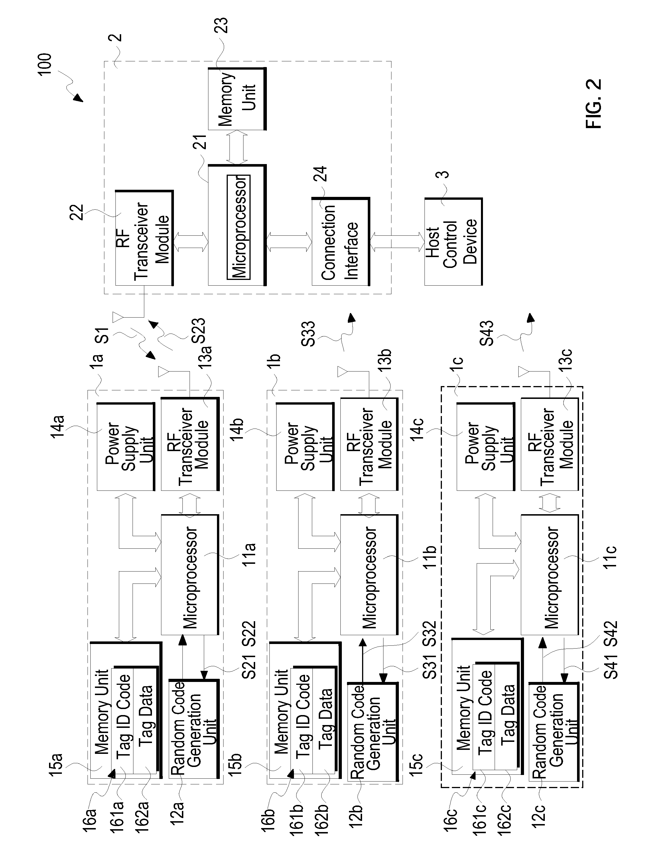
[0026]Referring to FIG. 2, which shows a system block diagram constituted by the components of the first embodiment of the present invention, as shown, the RFID tag 1a comprises a microprocessor 11a, which is connected to a random code generation unit 12a, a radio frequency transceiver module 13a, and a...

third embodiment

[0045]Referring to FIG. 7, which shows a timing chart that indicates that each RFID tag successively transmits packets in accordance with the third embodiment, in the instant embodiment, each RFID tag 1a, 1b, 1c is an active type RFID tag and thus no wake-up is necessary in carrying out successive transmission of signal.

[0046]As shown in the drawing, the instant embodiment is similar to those previous embodiments, but since the RFID tags 1a, 1b, 1c of the instant embodiment are active type, which allows successive transmission of signals. A time point when the RFID tag 1a, 1b, 1c starts to transmit signals is set as t01, t02, t03.

[0047]Firstly, each RFID tag 1a, 1b, 1c generates a random code (step 301). The generation of the random code is the same as that of the previous embodiments and can be generated by the random code generation unit on the basis of the base number generated by the microprocessor or the respective tag identification code.

[0048]Each RFID tag 1a, 1b, 1c bases on...


PUM


Abstract

A method for preventing signal collision in radio frequency identification (RFID) system through random code timing is disclosed. The RFID system includes one or more RFID reading device to receive respective tag information from a plurality of RFID tags. Multiple RFID tags of the RFID system each includes a microprocessor connected to a random code generation unit, a power supply unit, a memory unit and a radio frequency transceiver module. The memory unit stores the respective tag information that contains a tag identification code. The microprocessor of the RFID tag issues a base number or uses the tag identification code to generate a random code and a tag signal is transmitted to the RFID reading device in accordance with the random code so generated.

Description

FIELD OF THE INVENTION[0001]The present invention relates to wireless communication, in particular, to a method for preventing signal collision in radio frequency identification system through random code timing.BACKGROUND OF THE INVENTION[0002]A radio frequency identification (RFID) system is an advanced technique that uses radio waves to transmit data for realizing automatic object identification. The RFID system is generally comprised of two parts: an RFID tag and an RFID reading device or RFID reader.[0003]The RFID tag includes a chip that contains a unique identification (UID) code and an antenna unit, which are properly packed by means of special packaging technique. The RFID can be further divided in two classes, namely active type and passive type, based on the way how energy is supplied. A difference between the active type and the passive type resides in the fact that the active RFID includes a power source, such as a battery, while passive type does not. Due to such a rea...

Claims


Application Information

Patent Timeline
Patent Type & Authority Applications(United States)
IPC IPC(8): H04Q5/22
CPCG06K7/10059G06K7/0008
Inventor HSIEH, YUAN-NINGLEE, TA-YUNGPERNG, SHIN-YAO
Owner MITAC TECH CORP
Learn More