
Body exsiccation chamber

a body and exsiccation chamber technology, applied in the field of body exsiccation chambers, can solve the problems of time-consuming manufacture and installation, insufficient towel drying, complex construction, etc., and achieve the effects of convenient and comfortable removal of excess water, easy and inexpensive installation, and convenient adaptation to accommoda

Inactive Publication Date: 2010-03-04
ATTONITO JOSEPH FRANCIS
View PDF98 Cites 10 Cited by
  • Summary
  • Abstract
  • Description
  • Claims
  • Application Information

AI Technical Summary

Benefits of technology

[0017]The present invention provides a system and method to impinge a plurality of heated air streams evenly over the body of a person or animal to quickly and comfortably remove excess water. The invention overcomes the problems associated with the prior art by providing equal air flow from all of the nozzles of a drying chamber without the need for a complex manifold. Optionally, the air flow from the nozzles may be adjusted relative to each other such that when the air flow rate of the plenum from which they are fed changes, the air flow rates from each of the outlets change equally. In this manner, the air flow rates from each outlet maintain the same ratios with each other regardless of the overall flow rate of air into the plenum and chamber. The invention allows for adjustment of the air stream strength and temperature. The chamber is easy and inexpensive to install and is readily adapted to accommodate a veneer or alternative surfacing to enhance its aesthetic qualities.
[0022]It is therefore an object of the invention to provide a comfortable method of drying a living body or other object with use of a towel.

Problems solved by technology

Towel drying can be insufficient, particularly in a damp shower area, or in warm, humid weather.
It does not concentrate the heated air in a confined area and is therefore very inefficient.
This rapidly results in a complex, heavy structure that is time consuming to manufacture and install.
The structure requires multiple fans or other ventilators and is complex to construct.
Although this disclosure describes a method for distributing air pressure horizontally, it is ineffective in evenly distributing air pressure along the vertical axis.
However, the method disclosed for addressing this problem is limited in that it only is effective in a single, horizontal, direction and requires a crescent shaped plenum and substantially cylindrical chamber.

Method used


Image

  • Body exsiccation chamber
  • Body exsiccation chamber
  • Body exsiccation chamber

Examples


Embodiment Construction

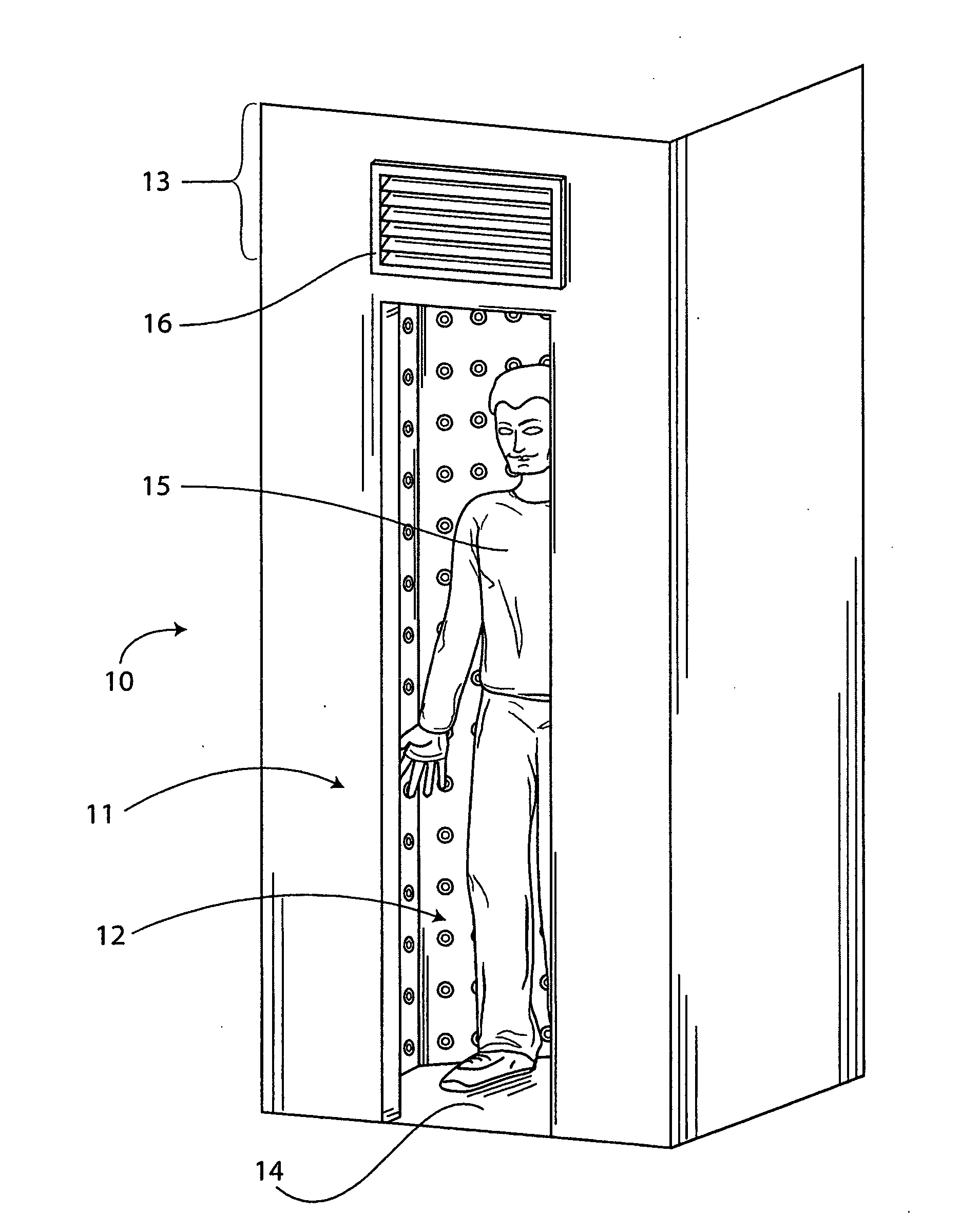
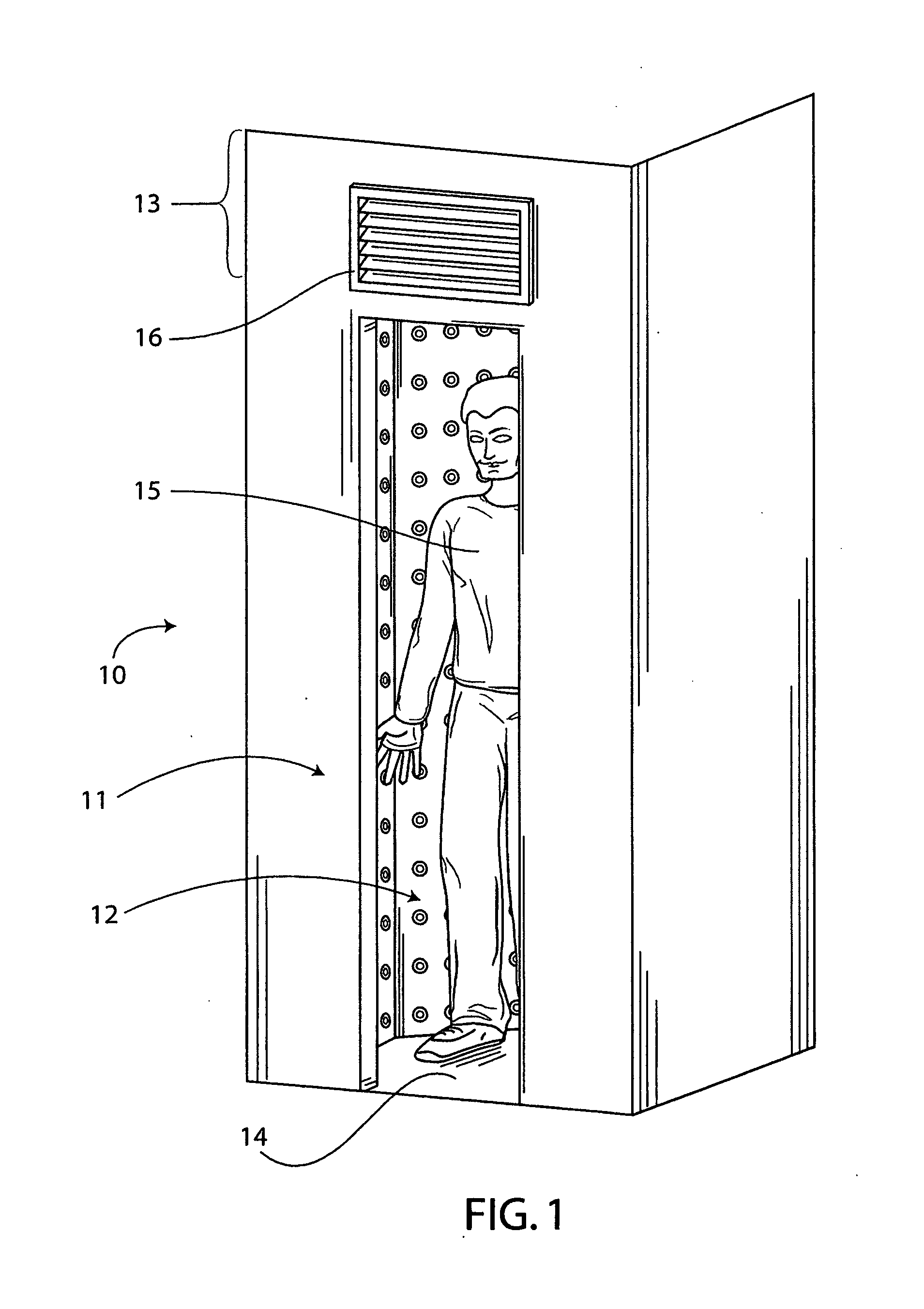
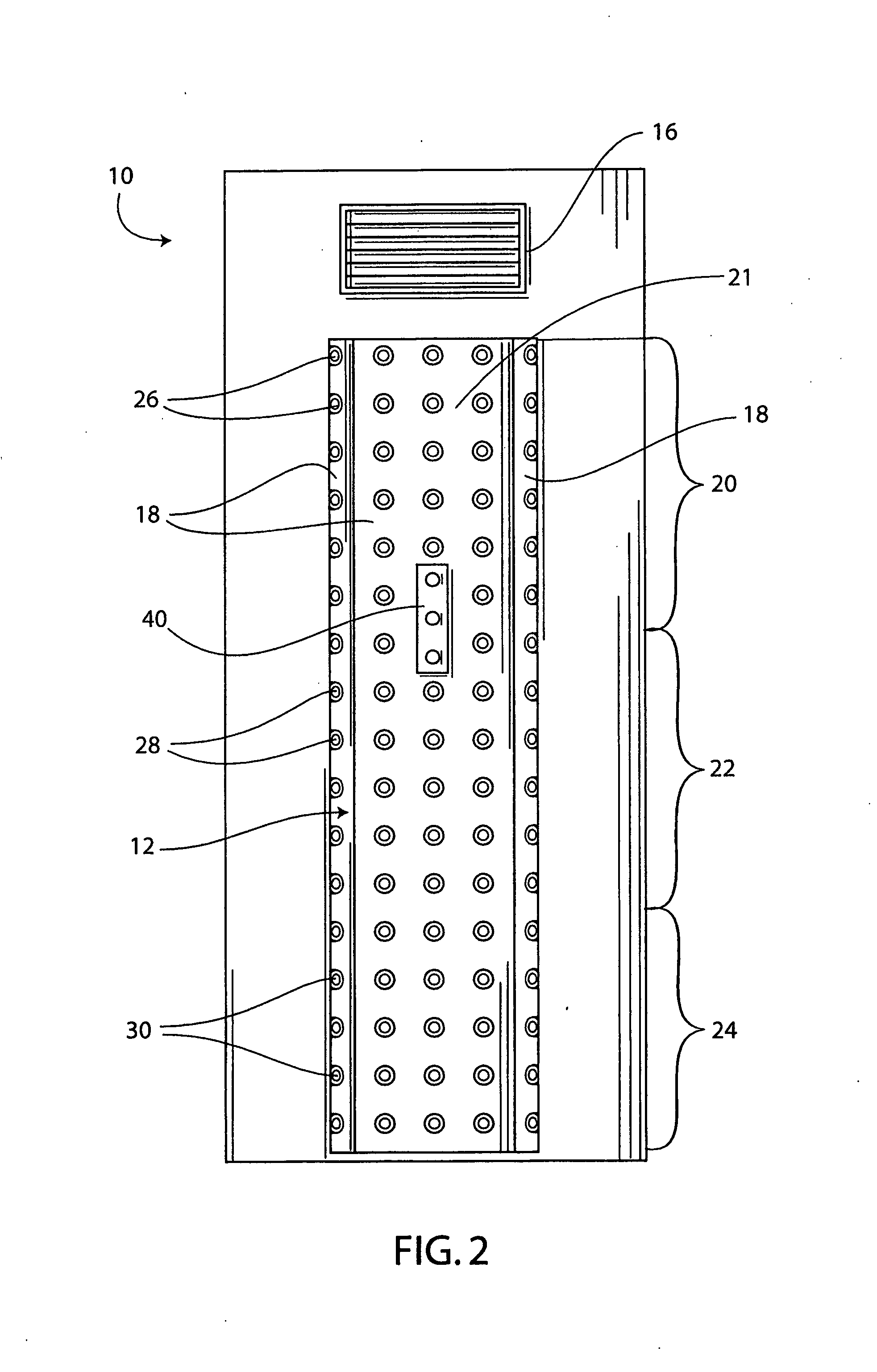
[0037]The exsiccation chamber of the present invention includes a chamber into which warm, drying air is fed by means of several apertures and / or nozzles in the walls of the chamber. A ventilator provides air to a plenum that surrounds the chamber. The ventilator receives air from an external vent and blows it across a heating element. The heated air enters the plenum formed between the walls of the drying chamber and an outer wall. Air exits the plenum and enters the chamber through several outlets in the chamber wall. The outlets vary in size, typically with larger outlets being located further from the plenum's air source. The airflow is adjusted such that air pressure from the outlets remains constant throughout the drying chamber. The outlets may optionally include interchangeable nozzles so that a person installing or providing maintenance to the chamber may adjust the relative air flow rates of the various nozzles to satisfy the preferences of the user or owner. For example, ...


PUM


Abstract

An exsiccation system provides a chamber for drying persons or animals in a fast, efficient and antibacterial manner. A series of apertures throughout the chamber provides jets of warm air directed onto a body in the chamber. The warm air removes moisture and exits out of the entrance to the chamber. The air flow into the chamber is optimized by adjusting the size of the outlets into the chamber. A control panel allows an operator to adjust the airflow and temperature of the exsiccation chamber.

Description

CROSS-REFERENCE TO RELATED APPLICATIONS[0001]NoneSTATEMENT REGARDING FEDERALLY SPONSORED RESEARCH OR DEVELOPMENT[0002]NoneREFERENCE TO SEQUENCE LISTING, A TABLE, OR A COMPUTER PROGRAM LISTING COMPACT DISC APPENDIX[0003]NoneBACKGROUND OF THE INVENTION[0004]1. Field of the Invention[0005]The present invention relates to an exsiccation apparatus and system for drying a body or other object. More specifically, the invention relates to a drying chamber for removing the exterior moisture of a person in a rapid, comfortable manner that discourages propagation of microorganisms.[0006]2. Prior Art[0007]Electric body dryers can be a convenient and clean replacement for towel drying. They reduce laundering costs and improve the unsanitary conditions associated with towel drying, particularly in locker rooms, hotels, and public washrooms. Problems of towel theft are also eliminated. A body dryer would also be useful in a home, as either a replacement for or supplement to towel drying. Towel dry...

Claims


Application Information

Patent Timeline
Patent Type & Authority Applications(United States)
IPC IPC(8): F26B25/06
CPCA47K10/48
Inventor ATTONITO, JOSEPH FRANCIS
Owner ATTONITO JOSEPH FRANCIS
Learn More