
Method of controlling robot for bridge inspection

a robot and bridge technology, applied in bridges, program control, instruments, etc., can solve the problems of large cost, inability to guarantee the safety of workers, and difficult periodic inspections with the naked ey

Inactive Publication Date: 2010-02-25
DEALIM IND & ACAD COOPERATION CENT +1
View PDF10 Cites 42 Cited by
  • Summary
  • Abstract
  • Description
  • Claims
  • Application Information

AI Technical Summary

Benefits of technology

[0008]Accordingly, the present invention has been made keeping in mind the above problems occurring in the prior art, and an object of the present invention is to provide a method of controlling a robot for bridge inspection, which moves a robot equipped with a camera to a desired location along a rail installed under a bridge, so that the status of the bridge is inspected, thus enabling real-time monitoring.

Problems solved by technology

Recently, methods of economically and efficiently performing the inspection of the appearance of the lower structure of a bridge, a periodic inspection difficult to conduct with the naked eye, have been required when inspection is conducted to examine the response level to aging of large-scale structures such as bridges.
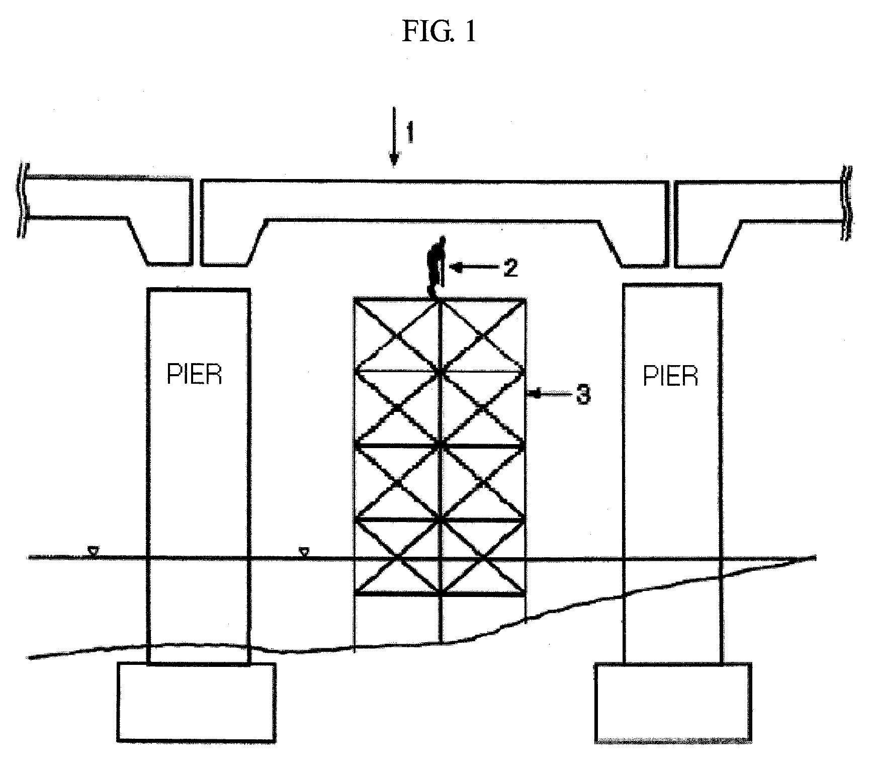
Such an inspection method is disadvantageous in that large costs are required to install the workbench such as a scaffold above the water under the bridge, and the safety of the worker cannot be guaranteed because the workbench sways due to strong winds on a windy day.
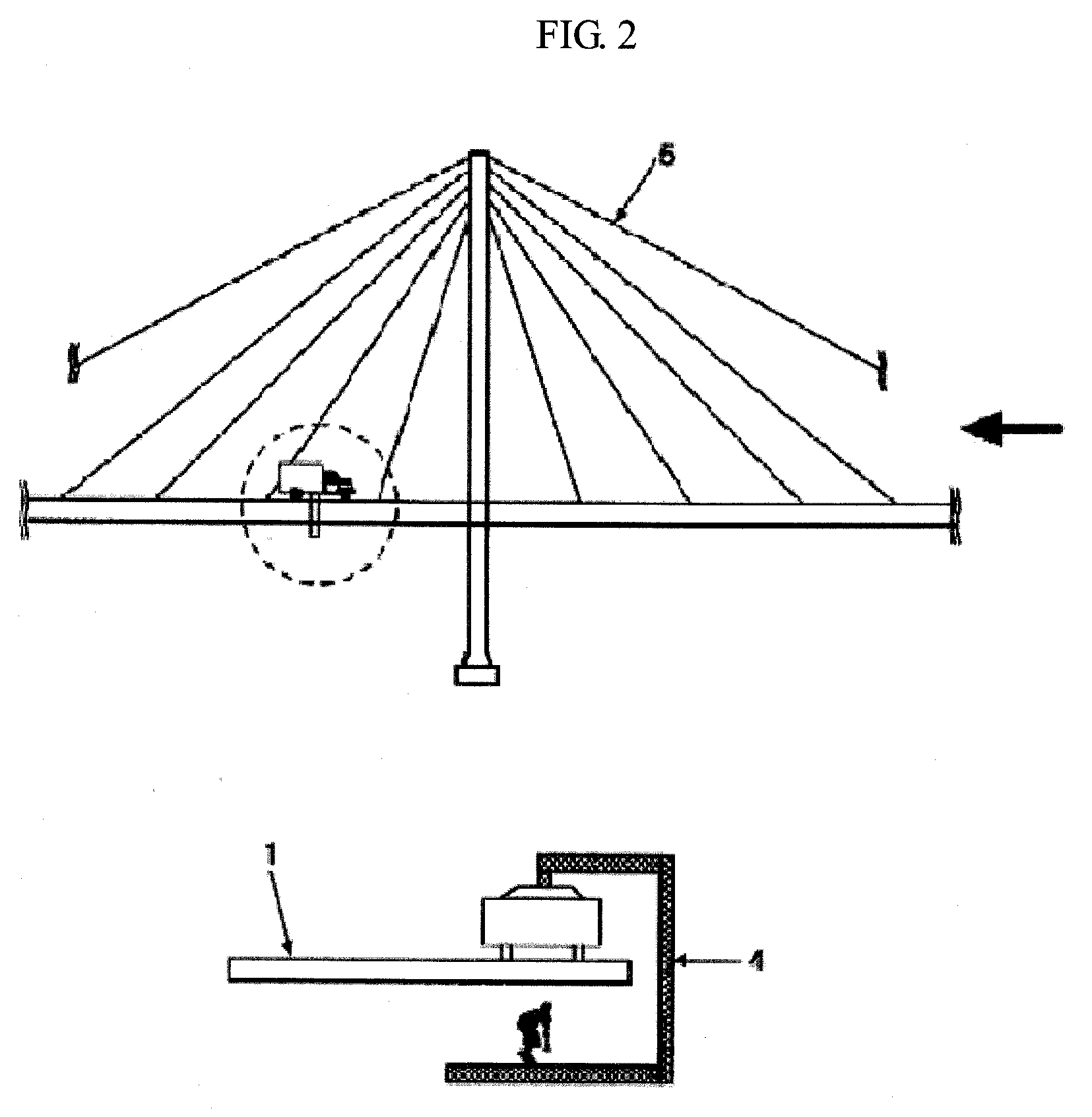
However, this method has a difficulty in that, in the case of a suspension bridge or a cable stayed bridge, the ladder must be moved each time to locations between respective cables, as shown in FIG. 2, and has a problem in that the safety of a worker cannot be guaranteed.

Method used


Image

  • Method of controlling robot for bridge inspection
  • Method of controlling robot for bridge inspection
  • Method of controlling robot for bridge inspection

Examples


Embodiment Construction

[0024]Hereinafter, embodiments of the present invention will be described in detail with reference to FIGS. 3 to 6.

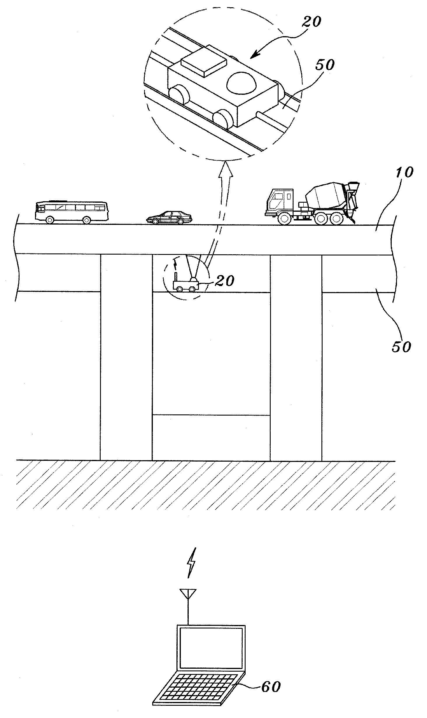
[0025]FIG. 3 is a schematic diagram showing the implementation of a robot system for bridge inspection applied to the present invention.

[0026]Referring to FIG. 3, the robot system includes a robot device 20 and a monitoring device 60 which are connected to each other to enable wireless communication. In this case, a rail 50 is installed between piers of the bridge, and the robot system includes the robot device 20 moving along the rail 50, and the monitoring device 60 configured to wirelessly control the robot device 20 and monitor the status of a deck 10 from image signals received from the robot device 20. The robot device 20 includes a motor, which is movable vertically and horizontally along the rail 50 and is rotatable, so as to inspect the status of the bottom of the deck 10.

[0027]Therefore, the robot device 20 is moved to a desired location in response to a contr...


PUM


Abstract

The present invention relates to a method of controlling a robot for bridge inspection. In the present invention, whether a defect image is being received from a robot device is determined. As a result of the determination, when the defect image is being received, a current location of the robot device is stored. Whether a predetermined period of time has been elapsed after the storage of the current location is determined. When the predetermined period of time has elapsed, a control command for moving the robot device to a prestored location is output. Whether a defect image at a same location as the prestored location is being received is determined. When the defect image at the same location is being received, a defect image at a previous time is compared with a defect image at a current time. A result of the comparison is displayed.

Description

BACKGROUND OF THE INVENTION[0001]1. Field of the Invention[0002]The present invention relates, in general, to a method of controlling a robot for bridge inspection, and, more particularly, to a method of controlling a robot for bridge inspection, which moves a robot equipped with a camera to a desired location along a rail installed under a bridge, thus inspecting the status of the bridge.[0003]2. Description of the Related Art[0004]Recently, methods of economically and efficiently performing the inspection of the appearance of the lower structure of a bridge, a periodic inspection difficult to conduct with the naked eye, have been required when inspection is conducted to examine the response level to aging of large-scale structures such as bridges.[0005]Industry-related basic facilities such as bridges are periodically examined for safety and inspected to guarantee their safety. Primarily, whether structures are cracked or corroded has been examined based on the inspection of appea...

Claims


Application Information

Patent Timeline
IPC IPC(8): G05B15/00
CPCE01D19/106B25J13/087B25J5/005
Inventor YANG, KYUNG-TAEK
Owner DEALIM IND & ACAD COOPERATION CENT
Learn More