Sputtering target including magnetic field uniformity enhancing sputtering target backing tube

a magnetic field and target technology, applied in the direction of vacuum evaporation coating, coating, electrolysis components, etc., can solve the problems of general disadvantages of short-range magnetic field variations, deviations in general uniformity, and inability to resolve short-range magnetic field variations through the use of shims, so as to reduce the occurrence of short-range magnetic field deviations and enhance the effect of magnetic field uniformity

Inactive Publication Date: 2010-02-25
GUARDIAN GLASS LLC
View PDF31 Cites 21 Cited by
  • Summary
  • Abstract
  • Description
  • Claims
  • Application Information

AI Technical Summary

Benefits of technology

[0004]As is known, the inclusion of magnet bars within target tubes enhances deposition rates. It is desirable to create substantially uniform magnetic fields, as a substantially uniform magnetic field generally leads to a more uniform coating on the substrate. Unfortunately, as stronger magnet bars are added to a target tube, deviations in the magnetic field uniformity become more and more likely, thus potentially leading to deviations in the uniformity of the coating. Such deviations in the uniformity generally are seen as disadvantageous. It is noted that some variations in magnetic field density sometimes are related to manufacturing imperfections in the magnet bars, misalignment of the magnet bars, and / or other factors.
[0006]Some commercially available magnet bars include approximately 5-6 bolt locations along a 10-12 foot magnet bar, enabling shims to be added or removed at these locations. For example, Applied Material's “X-Bar” magnet bar has a magnetic field adjustment shim spacing of 17.5 inches. Oftentimes, this sort of shimming effectively reduces long range magnetic field deviations.
[0011]Certain example embodiments of this invention provide magnetic field uniformity enhancing sputtering target backing tubes that may be used with a rotating sputtering targets. In certain example embodiments, the sputtering target backing tube may be slightly ferromagnetic to provide small-scale shunting, thereby reducing the occurrence of short-range magnetic field deviations. In certain example embodiments, backing tube alloys may be carefully optimized to be somewhat ferromagnetic, thereby enhancing the uniformity of the magnetic field generated by the magnet bar in magnetron sputtering with cylindrical sputtering targets.
[0013]In certain example embodiments, a rotatable magnetron sputtering target is provided. A rotatable target tube comprises a target backing tube having sputtering material supported by an outer surface thereof to be sputter deposited on a substrate. The target backing tube is at least partially ferromagnetic. A magnet bar structure is provided within the rotatable target tube. The magnet bar structure is stationary when the rotatable tube is rotating during sputtering. At least one adjustment mechanism is configured to alter a distance between at least a portion of the magnet bar structure and the sputtering material. The at least one screw or shim adjustment mechanism and the magnet bar structure are arranged to cooperate during sputtering to (a) improve or increase long range magnetic field uniformity and (b) reduce long range magnetic field deviations. The target backing tube and the magnet bar structure are arranged to cooperate during sputtering to (a) improve or increase short range magnetic field uniformity and (b) reduce short range magnetic field deviations.

Problems solved by technology

Unfortunately, as stronger magnet bars are added to a target tube, deviations in the magnetic field uniformity become more and more likely, thus potentially leading to deviations in the uniformity of the coating.
Such deviations in the uniformity generally are seen as disadvantageous.
Unfortunately, however, short range magnetic field variations generally cannot be resolved through the use of shims, as an unmanageable number of shim positions would have to be provided along the length of the magnet bar.
Indeed, any kind of fine-tuning is difficult because a large, typically rigid element is being adjusted.
Accordingly, tuning conventional long magnet bars (which typically extend the length of the target) tends to be comparatively less precise and may alter the magnetic field produced in potentially unpredictable and / or undesirable ways.
As noted above, it is difficult if not impossible to address short range magnetic field deviations in a commercially viable way through conventional shimming mechanisms.
For example, even Applied Material's “X-Bar” magnet bar cannot reasonably and reliably correct short range magnetic field deviations less than about 17.5 inches.

Method used


Image

  • Sputtering target including magnetic field uniformity enhancing sputtering target backing tube
  • Sputtering target including magnetic field uniformity enhancing sputtering target backing tube
  • Sputtering target including magnetic field uniformity enhancing sputtering target backing tube

Examples


Embodiment Construction

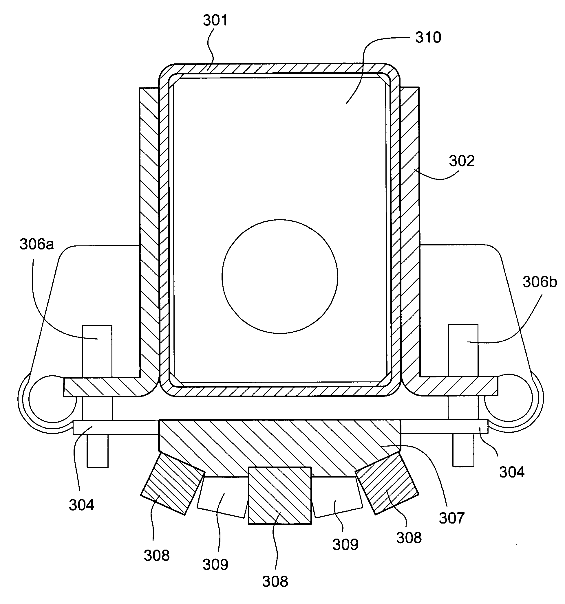
[0020]In certain example embodiments of this invention, a rotatable magnetron sputtering target is provided. A rotatable target tube comprises a target backing tube having sputtering material supported by an outer surface thereof to be sputter deposited on a substrate. The target backing tube is at least partially ferromagnetic. A magnet bar structure is provided within the rotatable target tube. The magnet bar structure is stationary when the rotatable tube is rotating during sputtering. The target backing tube and the magnet bar structure are arranged to cooperate in producing a substantially uniform magnetic field during sputtering.

[0021]In certain example embodiments, a rotatable magnetron sputtering target is provided. A rotatable target tube comprises a target backing tube having sputtering material supported by an outer surface thereof to be sputter deposited on a substrate. The target backing tube is at least partially ferromagnetic. A magnet bar structure is provided within...


PUM

PropertyMeasurementUnit
lengthaaaaaaaaaa
lengthaaaaaaaaaa
distanceaaaaaaaaaa

Abstract

Certain example embodiments relate to sputtering target backing tube that are slightly ferromagnetic, thereby providing small-scale shunting that reduces the occurrence or magnitude of short-range magnetic field deviations during magnetron sputtering with cylindrical sputtering targets. For example, backing tube allows may be carefully optimized to be somewhat ferromagnetic, thereby enhancing the uniformity of the magnetic field generated by the magnet bar. In certain example embodiments, short range magnetic field deviations may be reduced to less than about 5% from average, more preferably less than about 2% from average, and still more preferably less than about 1% from average. Such short range magnetic field deviation reducing target backing tubes may be used in along with, or in place of, shims or shunts that address long range magnetic field deviations.

Description

FIELD OF THE INVENTION[0001]Certain example embodiments of this invention relate to rotating sputtering targets. More particularly, certain example embodiments of this invention relate to magnetic field uniformity enhancing sputtering target backing tubes that may be used with rotating sputtering targets, and / or methods of making the same. In certain example embodiments, the sputtering target backing tube may be slightly ferromagnetic to provide small-scale shunting, thereby reducing the occurrence of short-range magnetic field deviations. In certain example embodiments, backing tube alloys may be carefully optimized to be somewhat ferromagnetic, thereby enhancing the uniformity of the magnetic field generated by the magnet bar in magnetron sputtering with cylindrical sputtering targets.BACKGROUND AND SUMMARY OF EXAMPLE EMBODIMENTS OF THE INVENTION[0002]The use of sputtering in order to deposit coatings on substrates is known in the art. For example, and without limitation, see U.S....

Claims


Application Information

Patent Timeline
Patent Type & Authority Applications(United States)
IPC IPC(8): C23C14/35
CPCC23C14/3407C23C14/35H01J37/3455H01J37/3452H01J37/3405
Inventor MILLER, GREGJACOBSON, DONALD V.
Owner GUARDIAN GLASS LLC
Why Eureka
Try Eureka