
Webcam module having a clamping device

Active Publication Date: 2010-02-18
LITE ON ELECTRONICS (GUANGZHOU) LTD +1
View PDF24 Cites 19 Cited by
  • Summary
  • Abstract
  • Description
  • Claims
  • Application Information

AI Technical Summary

Benefits of technology

[0008]The primary object of the present invention is to provide a webcam module having a clamping device. With its compact design, the volume and size of the webcam module can be reduced efficiently, thereby conforming to the requirements for the usage of the webcam module.
[0009]Another object of the present invention is to provide a webcam module having a clamping device, in which a torsion spring is disposed in a space within a body portion, thereby avoiding the torsion spring from being hit by external force. In this way, the lifetime and the quality of assembly of the webcam module can be increased.
[0012]Via to the above-mentioned structure, the webcam module having a clamping device can integrate an image module, a torsion element and other members into one body. Therefore, the present invention can reduce the volume of a portable electronic card connector effectively. Furthermore, the present invention utilizes a cover to cooperate with the body portion, so that the above components will not be exposed to the outside, thereby protecting them.
[0013]Furthermore, the cooperation between the sliding blocks and the guiding though-grooves allows the clips and the turning portions to be drivingly connected with each other, thereby generating more convenience in use and better additional value of the product of the webcam module.

Problems solved by technology

However, the conventional webcam cannot form a preferred mechanism with a base or clamping mount.
However, such a webcam has to be mounted to the base, so that the combined volume of the webcam and the base is too large, which may affect the operation of the user adversely.
Furthermore, the assembly of the webcam and the base lacks integration, so that the additional value of the product cannot be raised.
Since the elastic element is used to provide a clamping torsion force, the exposed elastic element may make it in danger of falling off or getting damaged easily by external force.
As a result, the above-mentioned webcam will lose its effect of clamping articles, which makes the user feel inconvenience in use.

Method used


Image

  • Webcam module having a clamping device
  • Webcam module having a clamping device
  • Webcam module having a clamping device

Examples


Embodiment Construction

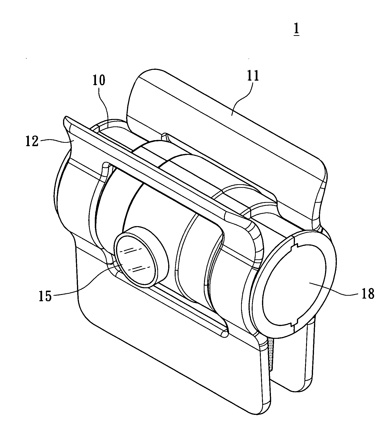
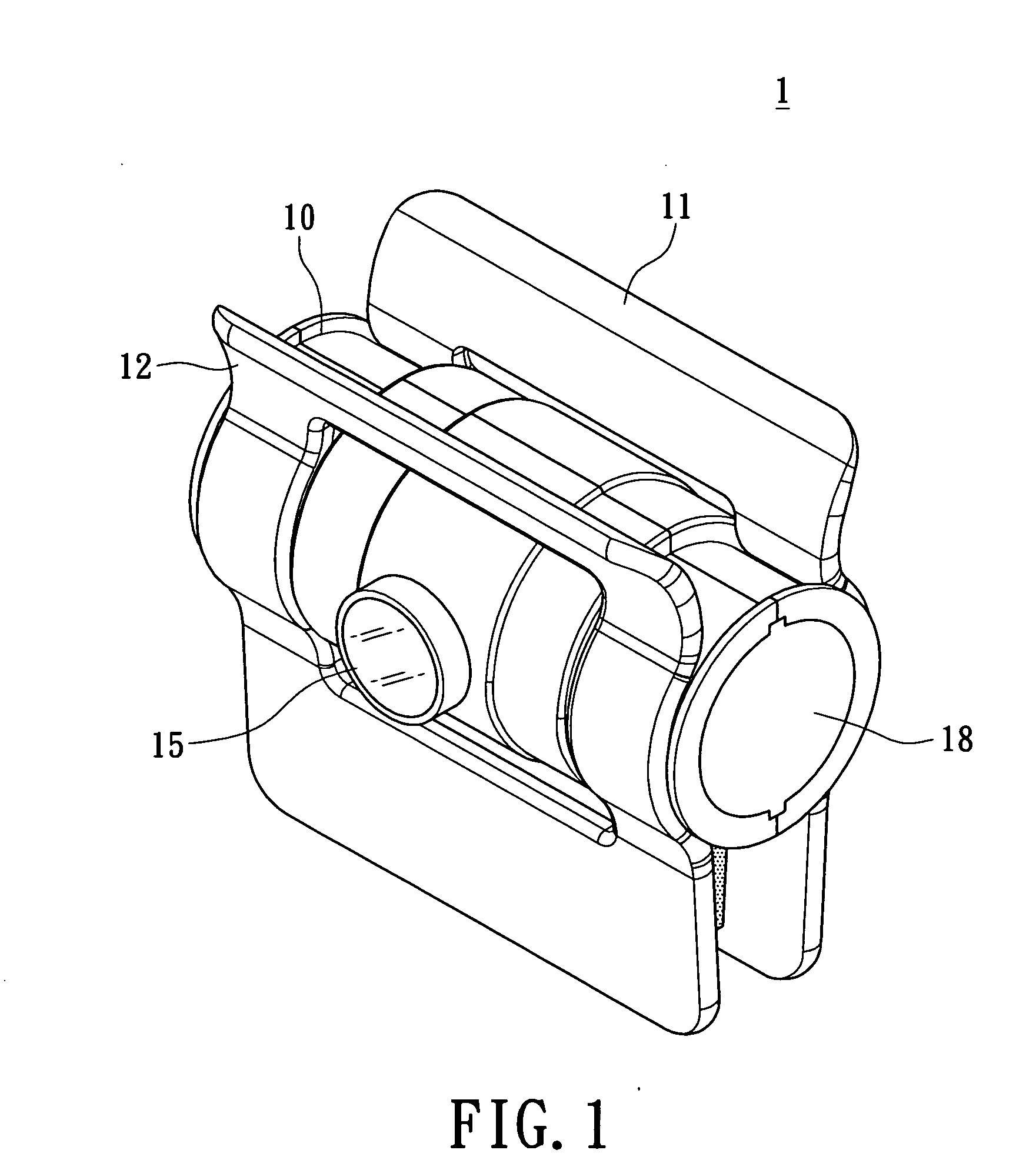
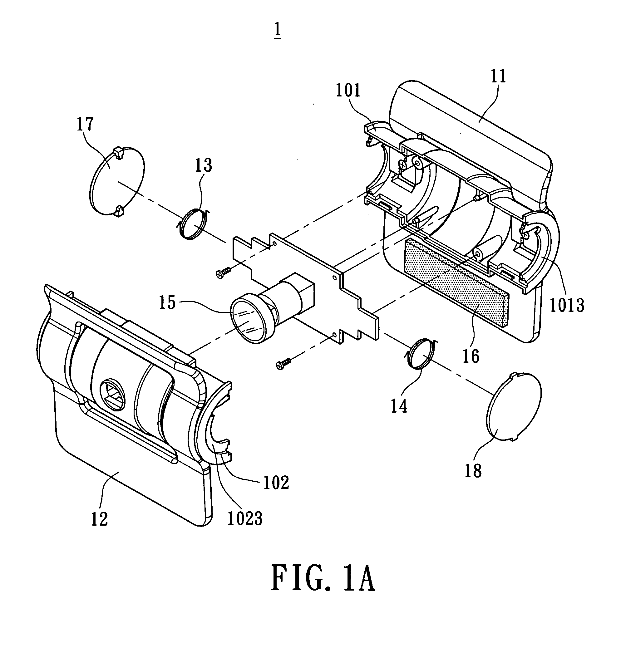
[0022]Please refer to FIGS. 1 to 4. The present invention provides a webcam module 1 having a clamping device. The webcam module 1 having a clamping device can be mounted to a predetermined position by means of a torsion force, such as a side frame of a liquid crystal screen 2 or other positions easy to be clamped. FIG. 1 and FIG. 1A are an assembled view and an exploded assembled view showing the webcam module 1 having a clamping device respectively. The webcam module 1 having a clamping device includes a body portion 10, a first sliding unit 11, a second sliding unit 12, a first torsion element 13 and a second torsion element 14. A description relating to the above units is made as follows.

[0023]Please refer to FIG. 2. The body portion 10 of the webcam module 1 having a clamping device is formed by a first casing 101 and a second casing 102. In the present embodiment, the body portion 10 is a cylindrical hollow body portion with an accommodated space 103. The first casing 101 and ...


PUM


Abstract

A webcam module having a clamping device includes a body portion, a first sliding unit, a second sliding unit, a first torsion element and a second torsion element. The first sliding unit and the second sliding unit are provided on the body portion. The first sliding unit is able to slide by means of the cooperation between the sliding block and the guiding though-groove. The torsion elements are used to generate a force for clamping an article. Via the above arrangement, a user can turn a first turning portion of the first sliding unit and a second turning portion of the second sliding unit, thereby opening a first clip and a second clip to a predetermined angle. The torsion elements allow the first clip and the second clip to be clamped at a predetermined position.

Description

BACKGROUND OF THE INVENTION[0001]1. Field of the Invention[0002]The present invention relates to a webcam module having a clamping device, and in particular to a webcam module which has high degree of integration and can be clamped on other devices.[0003]2. Description of Related Art[0004]With the continuous advancement of modern science technology, the speed of transmitting information is more and more amazing. The high speed achieved by a wired or wireless transmission allows people to grasp the messages all over the world very quickly, so that the concept of a global village is generated. With the widening of network bandwidth, word message cannot satisfy the information flow necessary for industries or individuals, so that the transmission of information containing pictures and voices are gradually developed. Therefore, webcams have been widely used in a picture information end of the Internet, whereby, for example, technical meetings held by providers and downstream manufacture...

Claims


Application Information

Patent Timeline
IPC IPC(8): H04N5/225
CPCH04N5/2252G06F1/1607H04N23/51
Inventor KAO, KUO-HUA
Owner LITE ON ELECTRONICS (GUANGZHOU) LTD
Learn More