
Triple-band antenna

a technology of antennas and antenna earthings, applied in the direction of resonant antennas, antenna earthings, elongated active element feeds, etc., can solve the problems of large volume of conventional dual-band antennas, inability to satisfy consumer desires, and occupies a relatively large spa

Inactive Publication Date: 2010-02-18
CHI MEI COMM SYST INC
View PDF4 Cites 10 Cited by
  • Summary
  • Abstract
  • Description
  • Claims
  • Application Information

AI Technical Summary

Problems solved by technology

The single band antenna provides only one frequency band for communication and cannot satisfy the consumer's desire that their electronic device be operated at multiple frequency bands.
However, the volume of the conventional dual-band antenna is relatively large, and occupies a relatively large space within the portable wireless communication device.
In addition, the conventional dual-band antenna is not suitable for developing a communicating system providing more than two frequency bands.

Method used


Image

  • Triple-band antenna
  • Triple-band antenna
  • Triple-band antenna

Examples


Embodiment Construction

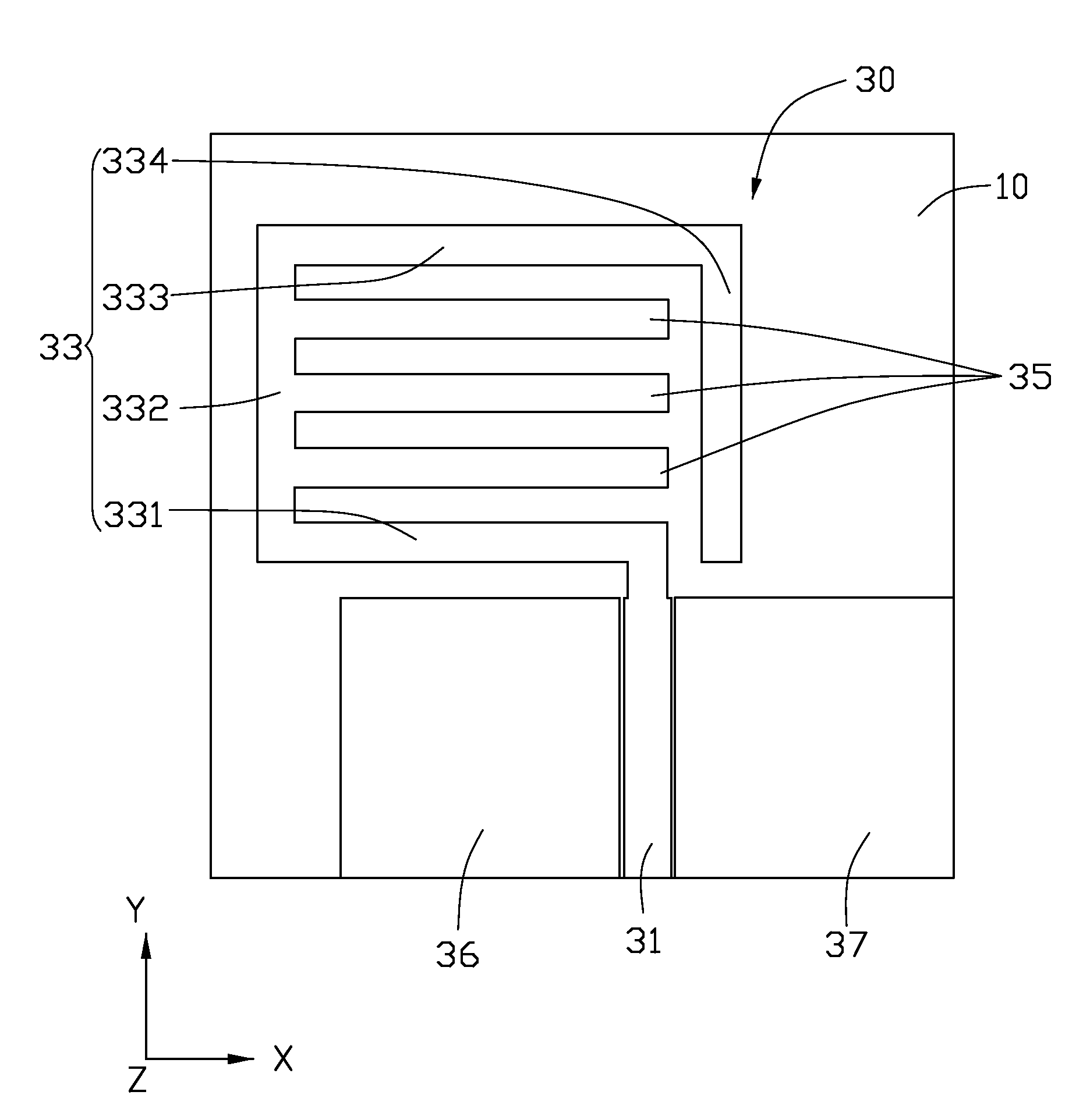
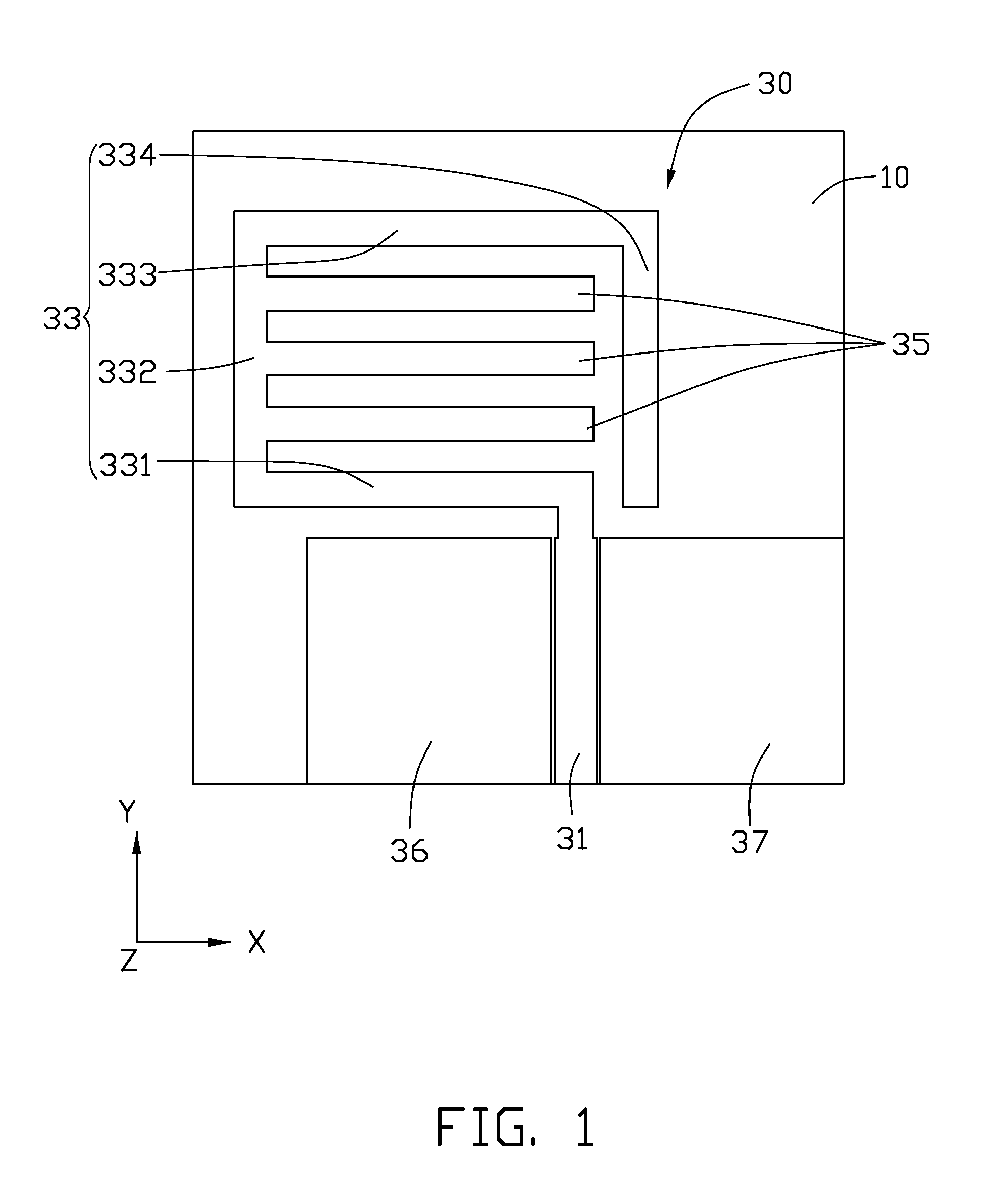
[0014]Referring to FIG. 1, a triple-band antenna 30 is a flat plane antenna according to an exemplary embodiment feeding signals using coplanar waveguides. The triple-band antenna 30 is disposed on an insulated board 10 of a portable wireless communication device (not shown) such as a mobile phone or personal digital assistant for transmitting and receiving signals, such as radio waves and datum signals. The insulated board 10 is a substantially rectangular board and may be made of fiberglass and may have a permittivity of about 4.4, a loss tangent of about 0.02, and a thickness of about 1.6 mm. In the exemplary embodiment, the triple-band antenna 30 is made of copper material and disposed on the insulated board 10 by engraving technology.

[0015]The triple-band antenna 30 includes a feed line 31, a first radiating body 33, a second radiating body 35, a first grounding sheet 36 and a second grounding sheet 37. The first radiating body 33 is a substantially rectangular sheet, having a ...


PUM


Abstract

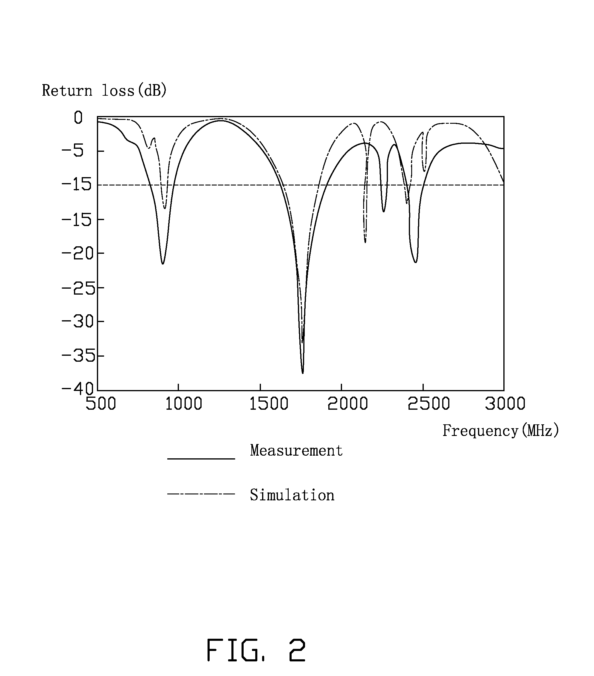
The disclosure discloses a triple-band antenna including a feed line, a first radiating body, a second radiating body and a grounding sheet. The first radiating body is a rectangular sheet. One end of the first radiating body is electrically connected with the end of the feed line. The second radiating body includes three parallel bar shape sheets extending from the first radiating body and surrounded by the first radiating body, and both share the feed line. The grounding sheet is disposed beside the feed line. The first radiating body and the second radiating body of the triple-band antenna generate three resonance frequencies according to the radio frequency received by the feed line to allow the triple-band antenna work under three different operating frequencies.

Description

BACKGROUND[0001]1. Technical Field[0002]The present disclosure generally relates to antennas for portable wireless communication devices, particularly to a triple-band antenna.[0003]2. Discussion of the Related Art[0004]With the developments of wireless communication and information processing technologies, portable wireless communication devices such as mobile phones and personal digital assistants (PDAs) are now in widespread use, and consumers may now enjoy the full convenience of high-end electronics products almost anytime and anywhere.[0005]Typical portable wireless communication devices generally include a single band antenna to transmit and receive electromagnetic waves. The single band antenna provides only one frequency band for communication and cannot satisfy the consumer's desire that their electronic device be operated at multiple frequency bands. A dual-band antenna can solve the aforesaid problems. However, the volume of the conventional dual-band antenna is relative...

Claims


Application Information

Patent Timeline
IPC IPC(8): H01Q5/00H01Q1/48H01Q1/38H01Q5/364
CPCH01Q1/243H01Q1/38H01Q5/364H01Q9/42H01Q9/40
Inventor CHANG, YU-MIN
Owner CHI MEI COMM SYST INC
Learn More