Interleaved slave switching circuit for discontinuous mode pfc converter

Inactive Publication Date: 2010-02-18
FAIRCHILD TAIWAN
View PDF3 Cites 10 Cited by
  • Summary
  • Abstract
  • Description
  • Claims
  • Application Information

AI Technical Summary

Benefits of technology

[0007]The present invention provides a slave switching circuit for a master-slave PFC converter. The slave switching circuit includes a phase-detection circuit coupled to detect a master-switching signal and a slave-inductor signal for generating a start signal and a phase-lock signal. The start signal is utilized to enable a slave-switching signal. The slave-switching signal is coupled to switch a slave inductor. An on-time-adjust circuit is coupled to adjust the on-time of the slave-switching signal in accordance with the phase-lock signal. The slave-inductor signal is correlated to the demagnetization of the slave inductor. The phase-lock signal is coupled to minimize the period between disablement of the slave-inductor signal and enablement of the start signal. A power management circuit is utilized to decrease the on-time of the slave-switching signal when the on-time of the master-switching signal is decreased and the pulse width is lower than a threshold.

Problems solved by technology

A high current demand normally decreases the power efficiency in a power converter.

Method used


Image

  • Interleaved slave switching circuit for discontinuous mode pfc converter
  • Interleaved slave switching circuit for discontinuous mode pfc converter
  • Interleaved slave switching circuit for discontinuous mode pfc converter

Examples


Embodiment Construction

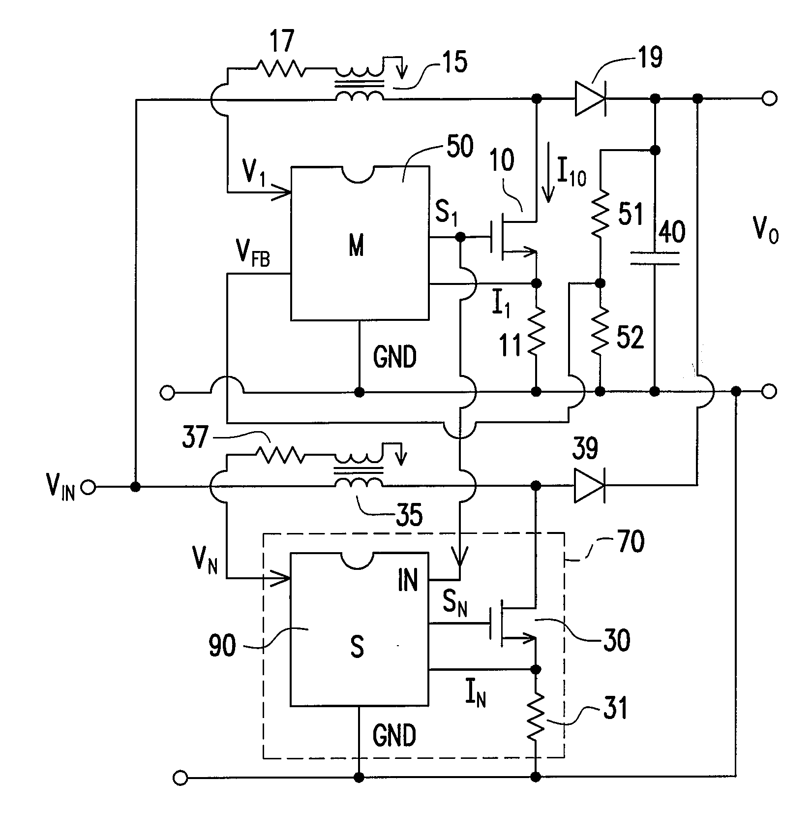
[0019]FIG. 1 shows a master-slave PFC converter according to the present invention. A master switching circuit 50, a transistor 10, a master inductor 15, and a rectifier 19 develop a master power converter. A master-switching signal S1 is coupled to control the transistor 10 for switching the master inductor 15. The rectifier 19 and a capacitor 40 are utilized to generate an output voltage VO of the PFC converter. A slave switching circuit 90, a transistor 30, a slave inductor 35, and a rectifier 39 develop a slave power converter coupled to the output voltage VO. A slave-switching signal SN is coupled to control the transistor 30 for switching the slave inductor 35. The outputs of the power converters are connected in parallel. The inductors 15 and 35 are connected to the output voltage VO. The inductors 15 and 35 are further coupled to an input terminal VIN. When the transistor 10 is turned on, a switching current I10 is generated. It is given by,

I10=VINL15×TON-1,(2)

[0020]wherein ...


PUM


Abstract

A slave switching circuit for a master-slave PFC converter is disclosed. The slave switching circuit includes a phase-detection circuit coupled to detect a master-switching signal and a slave-inductor signal for generating a start signal and a phase-lock signal. The start signal is coupled to enable a slave-switching signal. The slave-switching signal is coupled to switch a slave inductor. An on-time-adjust circuit is used to adjust the on-time of the slave-switching signal in accordance with the phase-lock signal. The slave-inductor signal is correlated to the demagnetization of the slave inductor. The phase-lock signal is coupled to minimize the period between the disablement of the slave-inductor signal and the enablement of the start signal.

Description

BACKGROUND OF THE INVENTION[0001]1. Field of the Invention[0002]The present invention relates to a switching power converter, and more particularly to a control circuit of power factor correction (PFC) converters.[0003]2. Description of the Related Art[0004]A high current demand normally decreases the power efficiency in a power converter. The power loss of the power converter is exponentially proportional to its current.PLOSS=I2×R   (1),[0005]wherein I is a switching current of the power converter; R is an impedance of switching devices such as a resistance of an inductor and a transistor, etc.[0006]Therefore, parallel technologies are developed for reducing the power consumption of the power converter. A PFC converter is utilized to improve a power factor of an AC power source. The detailed skill of a PFC circuit can be found in prior arts, such as U.S. Pat. No. 7,116,090, entitled “Switching Control Circuit for Discontinuous Mode PFC Converters”. The present invention is directed...

Claims


Application Information

Patent Timeline
IPC IPC(8): G05F1/40
CPCH02M1/42H02M3/1584Y02B70/126H02M2003/1586Y02B70/12H02M2001/4291Y02B70/10Y02P80/10H02M1/4291H02M3/1586
Inventor YANG, TA-YUNG
Owner FAIRCHILD TAIWAN
Why Eureka
Try Eureka