
Device for indirectly measuring occlusal forces

a technology of occlusal force and indirect measurement, which is applied in the field of indirect measurement of occlusal force, can solve the problems of severe direct and indirect pathological consequences for patients

Inactive Publication Date: 2010-02-11
SENSE INSIDE GMBH
View PDF7 Cites 30 Cited by
  • Summary
  • Abstract
  • Description
  • Claims
  • Application Information

AI Technical Summary

Benefits of technology

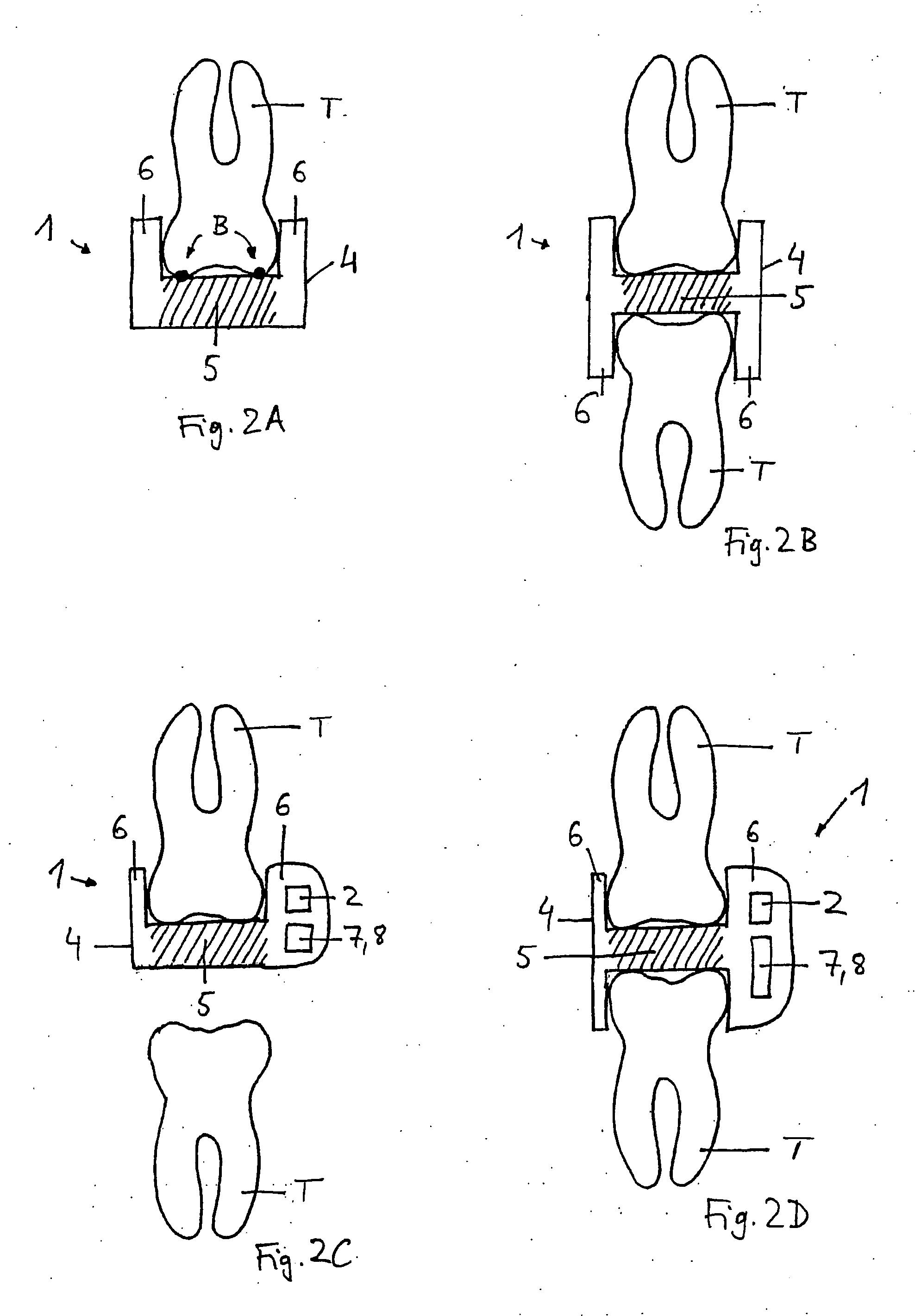
[0032]A least two sensors can be completely arranged within one of each of the different regions having different mechanical properties, with the result that, for example, one sensor is arranged within a first region of the support having a first hardness and a second sensor is arranged within a region of the support having a second hardness. This arrangement allows drawing comparisons between the effects of forces on the different regions, wherein said comparisons can be used for the evaluation of the measured data and, in particular, for the localization and the quantitative determination of a pressure. To achieve this according to the invention, at least two sensors can also be arranged adjacent to at least two different regions having different physical and / or mechanical properties, so that they are not completely positioned within the different regions.

Problems solved by technology

In addition to disturbing effects, such as grinding of the teeth, this also results in severe direct and indirect pathological consequences for the patient, for example wear of the teeth, overload of the periodontium, the mandibular joint and the masticatory muscles, tinnitus or vertigo.

Method used


Image

  • Device for indirectly measuring occlusal forces
  • Device for indirectly measuring occlusal forces
  • Device for indirectly measuring occlusal forces

Examples


Embodiment Construction

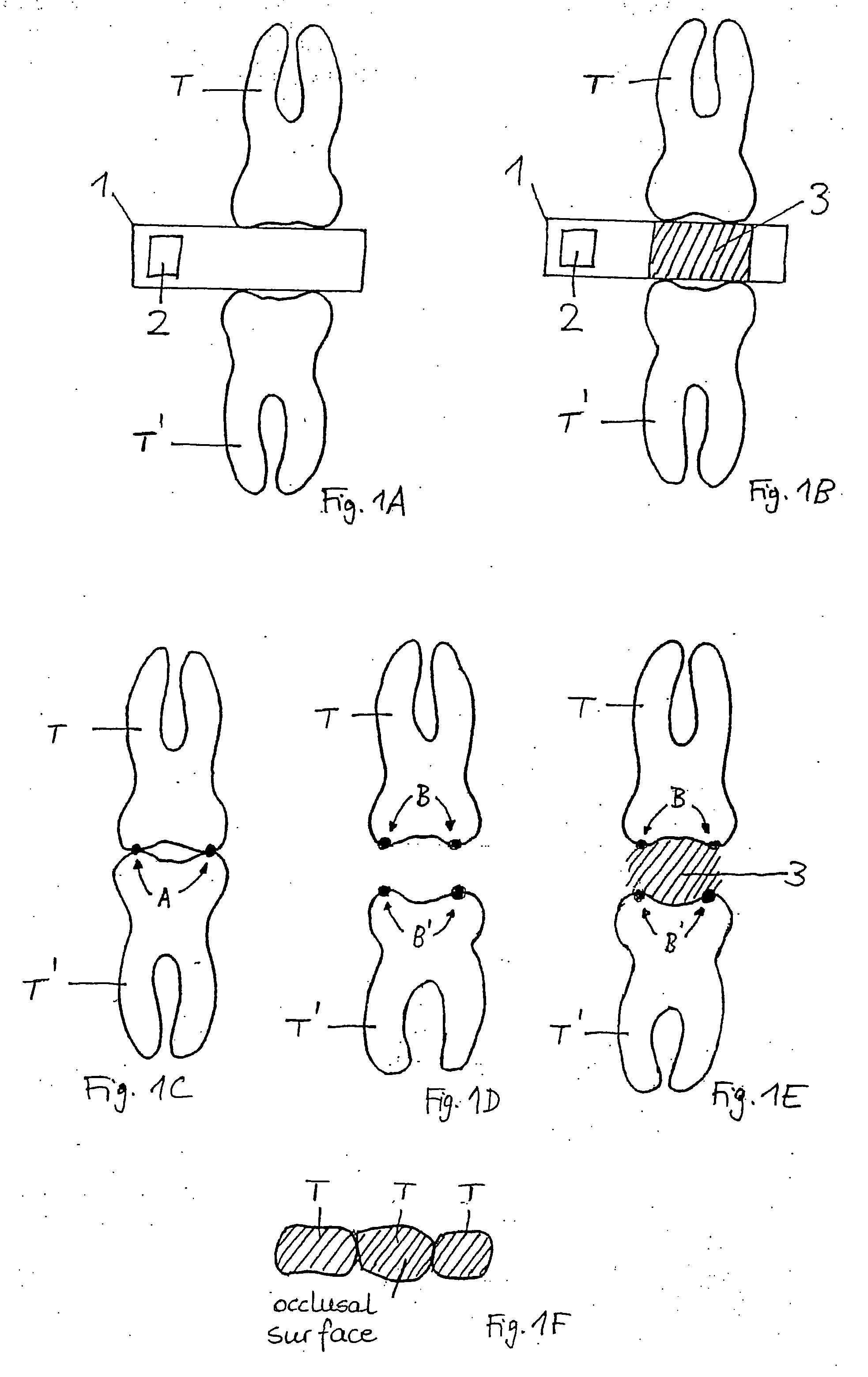
[0049]FIG. 1A shows a schematic diagram of an apparatus 1 according to the invention for the measurement of occlusal forces in case of a terminal occlusion of teeth comprising a sensor 2. The figure shows the position of a tooth T, T′ each of the upper jaw and the lower jaw in case of a terminal occlusion with the apparatus 1.

[0050]FIG. 1B shows the apparatus 1 according to FIG. 1A and, furthermore, illustrates that the sensor 2 is arranged outside of an occlusion zone 3 of the teeth T, T′. To provide a better understanding of the occlusion zone 3, reference is made to the following figures, in particular to FIG. 1E.

[0051]To illustrate the term occlusion zone, FIG. 1C shows two antagonistic teeth T, T′ in case of a terminal occlusion. Herein, points A represent the occlusion points of the teeth T, T′, i.e. those points where the upper and the lower teeth T, T′ come into contact in case of a terminal occlusion. We speak of occlusion points although the zone of antagonistic contact ma...


PUM


Abstract

An apparatus, in particular a dental splint, for the measurement of occlusal forces in case of a terminal occlusion of teeth comprises at least one sensor which is arranged outside of an occlusion region of the apparatus. A system for the diagnosis or treatment of bruxism serves to determine the position or the size of occlusal forces on the apparatus. A method allows exact localization and quantitative determination of occlusal forces on the apparatus.

Description

[0001]This application is a National Stage application of International Application No. PCT / EP2008 / 001442, filed on Feb. 22, 2008 and claims priority of German Application Serial No. DE 10 2007 009 910.1 filed Feb. 27, 2007.BACKGROUND OF THE INVENTION[0002]1. Field of the Invention[0003]The invention relates to an apparatus, in particular a dental splint, comprising at least one sensor, for the measurement of occlusal forces in case of a terminal occlusion of teeth. Furthermore, the invention relates to a system for the diagnosis or treatment of bruxism. In addition, the invention relates to a method for the determination of the position or the size of occlusal forces on the apparatus.[0004]2. Description of the Prior Art[0005]Dental splints which can be attached to one or a plurality of teeth and are intended to assume various tasks have already been used within the scope of various diagnostic or therapeutic methods in medicine and / or dentistry. Diverse dental splints are, in parti...

Claims


Application Information

Patent Timeline
IPC IPC(8): A61B5/11
CPCA61B5/0002A61B5/228A61B5/682A61B5/4557A61B5/4528
Inventor SCHOLZ, ALEXANDERCLAUSS, JOHANNES
Owner SENSE INSIDE GMBH
Learn More