Energy Generation System for Reduced Visual Pollution and Cost

a technology of energy generation system and visual pollution, applied in the direction of electric generator control, machine/engine, greenhouse gas reduction, etc., can solve the problems of wind system being used, system can only be depended on to provide about 10% to 15% of the total, and system is not stable, so as to achieve small or less noticeable or more inexpensive

Inactive Publication Date: 2010-02-11
STEPHANY TIMOTHY JOSEPH
View PDF12 Cites 3 Cited by
  • Summary
  • Abstract
  • Description
  • Claims
  • Application Information

AI Technical Summary

Benefits of technology

[0004]The object of this invention to be a system in which small and inconspicuous energy generation units are used that can be distributed throughout a city and surrounding country with no perceived visual pollution. Two fundamental systems are proposed for the conveyance of energy from the individual units designed to be unobtrusive that are connected through fluid, pipe, shaft, or conduit to an ener...

Problems solved by technology

The main drawback is that the wind is not steady and backup systems to provide electrical power are needed during periods of insufficient wind velocity. as a result wind a systems can only be depended upon to provide about 10% to 15% of the total power since it is uneconomical to exceed this level by constructing backup systems that are seldom used.
Present wind systems being used suffer from an additional problem: the construction of large towers with propellers several hundred feet long is a distraction and irritation to scenery and many people object to the hypnotic effect of a large number of these systems located near...

Method used


Image

  • Energy Generation System for Reduced Visual Pollution and Cost
  • Energy Generation System for Reduced Visual Pollution and Cost
  • Energy Generation System for Reduced Visual Pollution and Cost

Examples


Embodiment Construction

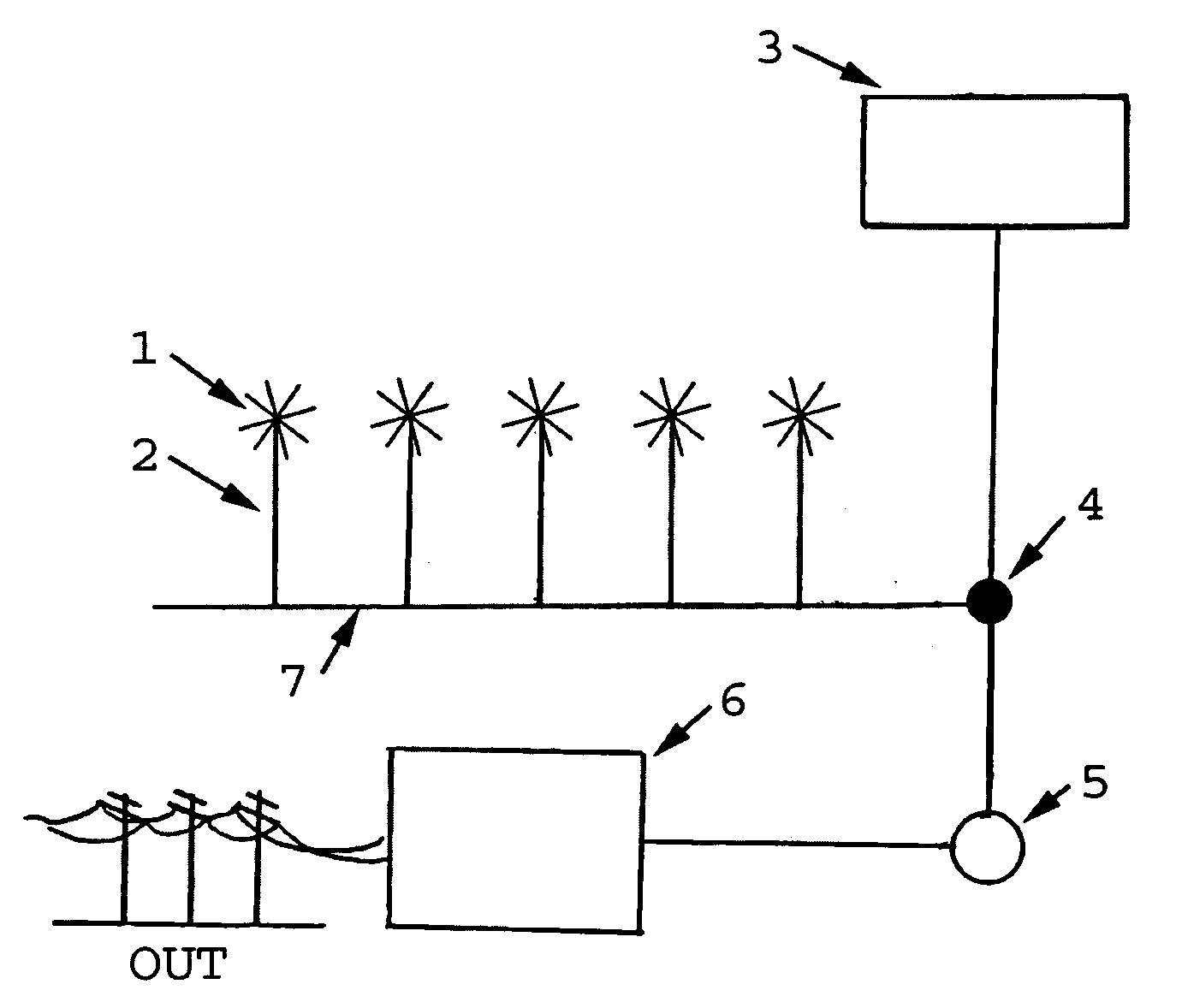
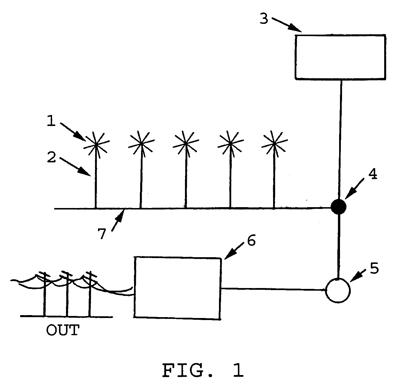
[0010]Now in reference to FIG. 1 which shows a configuration of the system with the transmission of energy as captured through an array of propellers 1 that are shown upon shafts 2 that pump fluid through a conduit transmission system 7 that passes through a pump station 4 that conveys some proportion to a storage tank 3 and some proportion to turn a turbine 5, with the turbine connected to an electrical generator 6. The invention incorporates a storage system so the system can store power during periods when excess energy is produced and then used when the harnessers are not capturing sufficient energy. The storage system can be an elevated storage tank (an ideal fluid would be water). At the times that energy is being harnessed which exceed the needed amount, the excess fluid can be directed to the storage tank. When the capturing system is not producing sufficient power to meet the amount needed, the fluid runs down to produces a power output by turning the turbine as in a conven...


PUM


Abstract

This invention is an improvement on systems that use wind to generate electrical power. It reduces visual pollution and cost, and increases the system efficiency over the prior art of wind powered electrical generators. The proposed system uses a plurality of wind-driven energy harnessers or propellers connected to one or a very few electrical generators, replacing the multiplicity of individual wind-power propellers each connected separately to its own generator. It permits better flexibility in design to reduce or unwanted effects, such as visual pollution which is a major problem with present state of the art wind generating plants. The invention also incorporates a storage system to produce energy during period when the harnessers are not capturing sufficient energy from the wind to provide the electrical power needed. The electrical power generated can then be connected to a power grid or other energy network to provide useful energy.

Description

BACKGROUND OF THE INVENTION[0001]Using the wind to drive electrical alternators to provide power to our homes and industry represents a fuel-less method resulting in no pollution. The main drawback is that the wind is not steady and backup systems to provide electrical power are needed during periods of insufficient wind velocity. as a result wind a systems can only be depended upon to provide about 10% to 15% of the total power since it is uneconomical to exceed this level by constructing backup systems that are seldom used.[0002]Present wind systems being used suffer from an additional problem: the construction of large towers with propellers several hundred feet long is a distraction and irritation to scenery and many people object to the hypnotic effect of a large number of these systems located near each other and in the areas of populated land. They are a visual nuisance that may be distracting and are prone to fragmentation during high-velocity winds, creating large projectil...

Claims


Application Information

Patent Timeline
IPC IPC(8): F03D1/02
CPCF03D9/00F05B2220/706Y02E10/725F05B2240/96F05B2240/40Y02E10/72Y02E70/30F03D1/02F03D9/255F03D9/11
Inventor STEPHANY, TIMOTHY JOSEPH
Owner STEPHANY TIMOTHY JOSEPH
Why Eureka
Try Eureka