
Precision orifice safety device

a safety device and orifice technology, applied in the direction of suction devices, intravenous devices, other medical devices, etc., can solve the problems of increased vacuum in the aspiration conduit, common and dangerous ophthalmic surgery, serious damage to the eye of patients, etc., to improve the control of fluid flow

Inactive Publication Date: 2010-02-04
BAUSCH & LOMB INC
View PDF7 Cites 45 Cited by
  • Summary
  • Abstract
  • Description
  • Claims
  • Application Information

AI Technical Summary

Benefits of technology

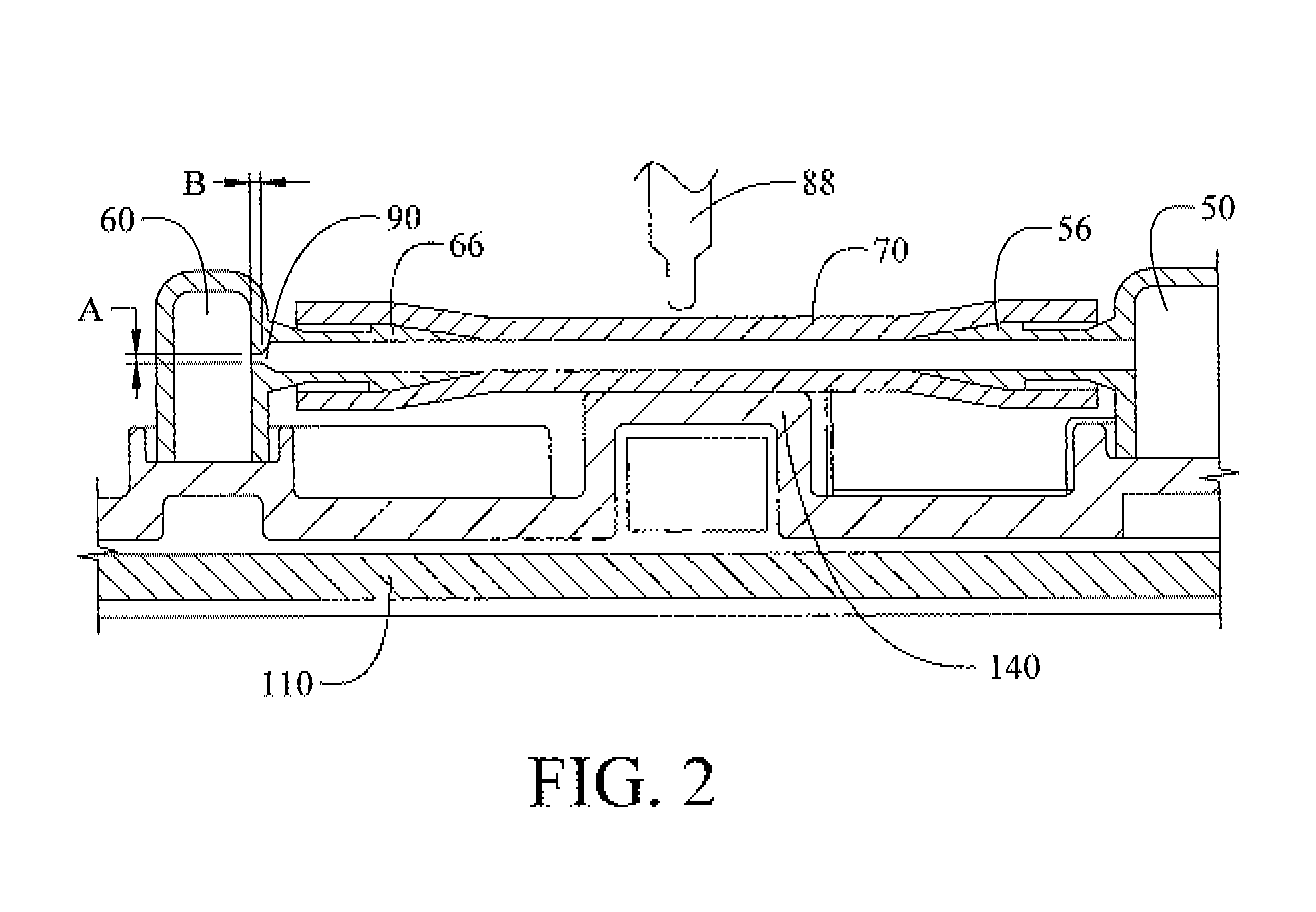
The present invention provides a safety device in a fluid vent path for an ophthalmic surgical system to control fluid flow and reduce vacuum level. The safety device includes an orifice with a large cross-sectional area to allow an acceptable amount of fluid to flow into the aspiration conduit and provide adequate reflux, while also restricting the flow of fluid to allow enough fluid to continue to flow from the irrigation source to a handpiece at a surgical site. The invention also includes an irrigation manifold and a fluid vent conduit with an orifice, which allows valves of the surgical console to control the flow of irrigation fluid and aspirant fluid, and provides adequate reflux. The surgical system also includes a collection cassette, a pump for creating a vacuum, a handpiece, an irrigation conduit, an aspiration conduit, and a safety device for maintaining a controlled fluid flow.

Problems solved by technology

A common and dangerous occurrence in ophthalmic surgery is post-occlusion surge.
On occasion bits of tissue are larger than the aspiration lumen at the tip of the phaco handpiece, which can occlude the tip and cause an increase in vacuum in the aspiration conduit.
Post-occlusion surge can cause serious damage to a patient's eye.
Generally speaking, uncontrolled-bypassing flow could result in undesirable effects in removing cataract.
For example, under-influx could not be effective to equalize the negative pressure built therein and over-influx could prevent sufficient amount of the irrigation fluid from flowing to a handpiece.

Method used


Image

  • Precision orifice safety device
  • Precision orifice safety device
  • Precision orifice safety device

Examples


Embodiment Construction

[0015]The following description is merely exemplary in nature and is not intended to limit the present disclosure, application, or uses.

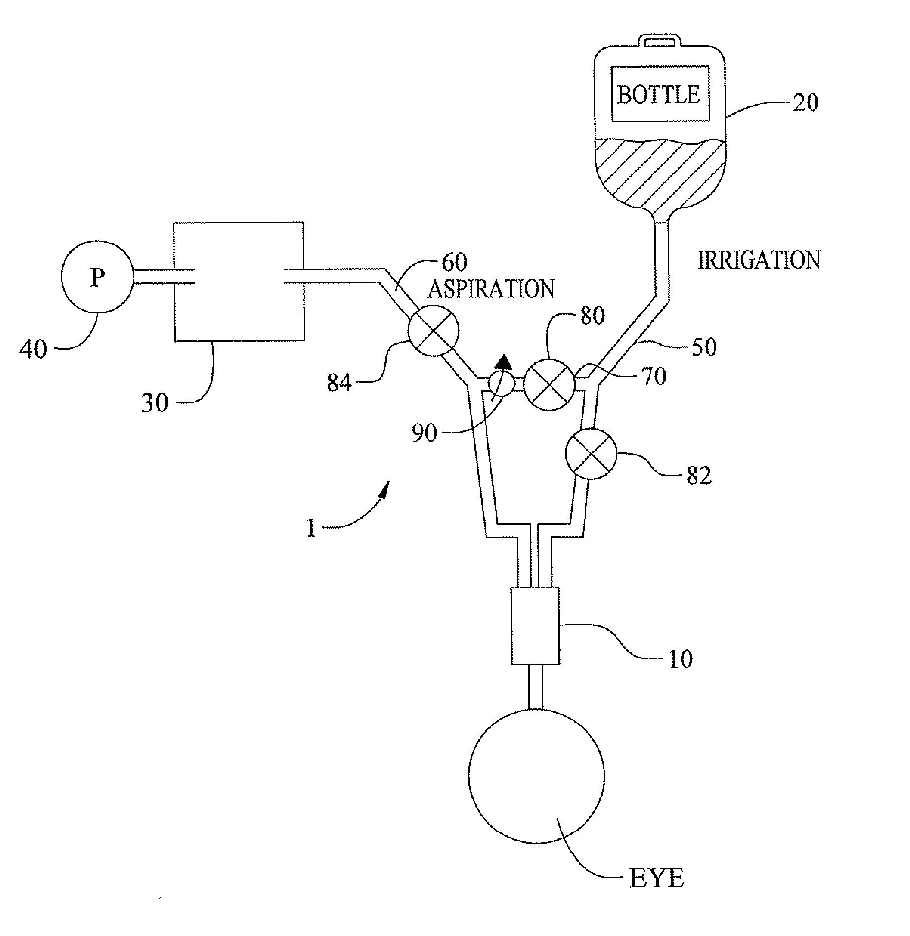
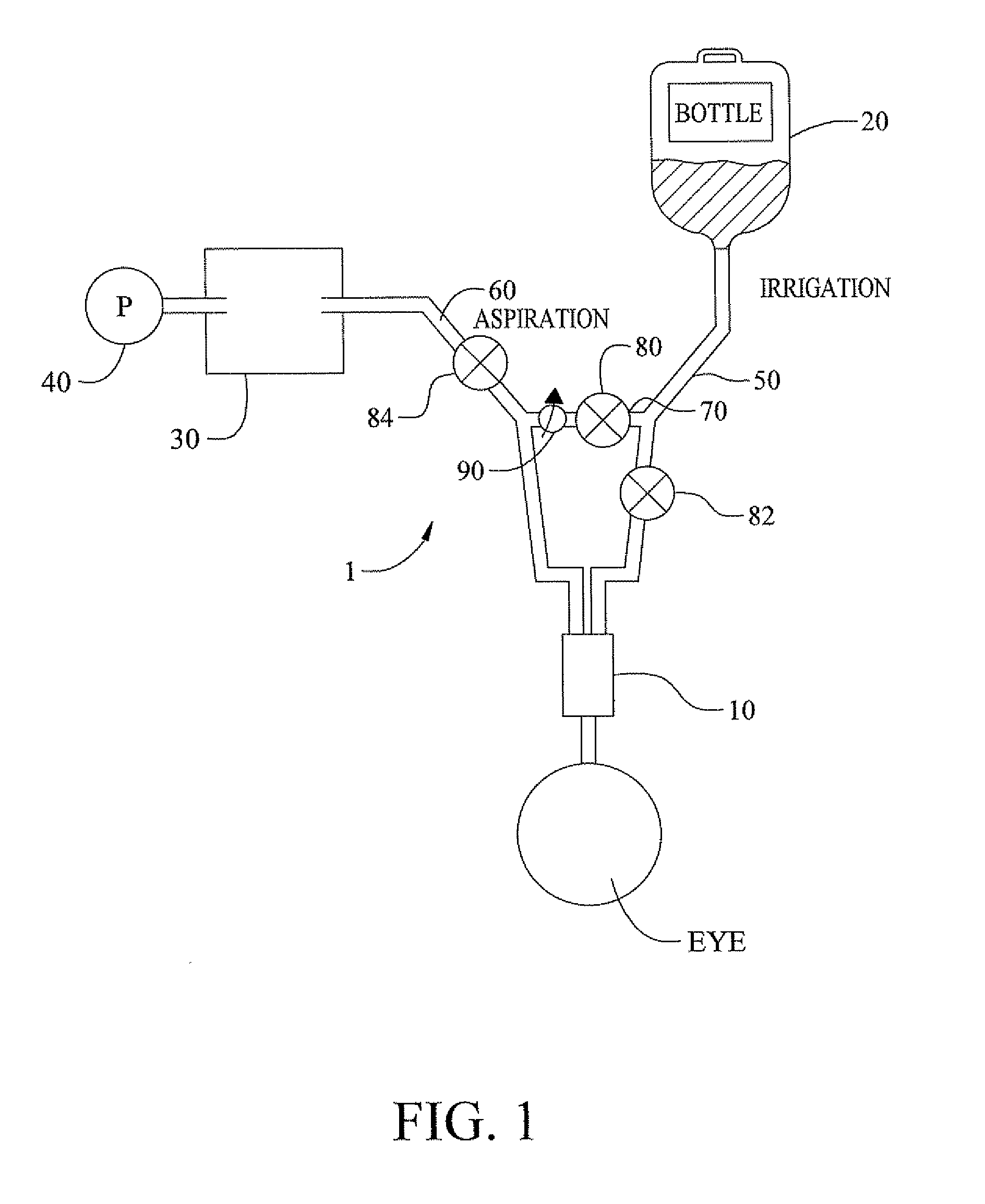
[0016]Referring to FIG. 1, an ophthalmic surgical system 1, in accordance with an embodiment, comprises a surgical handpiece 10, a source of irrigation fluid 20, a collection cassette 30, a vacuum pump 40, an irrigation conduit 50 connecting the surgical handpiece to the irrigation fluid source and an aspiration conduit 60 connecting the surgical handpiece to the vacuum pump 40 and the collection cassette 30, a fluid vent conduit 70 the ends of which ends are connected to the irrigation conduit 50 and the aspiration conduit 60 respectively, valves 80, 82, 84 disposed at various locations within the circuit, and a safety device 90 for maintaining a controlled fluid flow formed within the fluid vent conduit 70. The surgical system 1 is particularly useful in ophthalmic surgery where it is necessary to break up and remove undesirable biological materia...


PUM


Abstract

A safety device in a fluid vent conduit for reducing vacuum level in an aspiration conduit of an ophthalmic surgical system. The device includes an orifice having an inlet for receiving a flow of fluid from an irrigation source. The orifice further has an outlet for directing the flow of fluid into the aspiration conduit. The orifice has a cross-sectional area sufficiently large to ensure an acceptable amount of fluid flows into the aspiration conduit, to reduce the vacuum level in the aspiration conduit, to an acceptable level in an acceptable amount of time and to provide adequate reflux. The cross-section area is sufficiently small to restrict the flow of fluid to allow enough fluid to continue to flow from the irrigation source to a handpiece at a surgical site.

Description

FIELD[0001]The present invention relates generally to a device for controlling a fluid flow in a system used in various surgical procedures. More specifically, it relates to a safety device for providing improved fluid control in an ophthalmic surgical system to maintain an appropriate intra-pressure within a conduit of the surgical system.BACKGROUND[0002]A cataract is an opacity that develops in the crystalline lens of the eye or in its envelope. One medical procedure to remove a cataract-affected lens is phacoemulsification using ultrasonic sound to break up or emulsify the cataract. A phacoemulsification machine typically includes a handpiece with both irrigation and aspiration functions. A phaco handpiece sucks-in or aspirates emulsified fluids and simultaneously replaces those aspirated fluids with irrigation fluid, typically balanced salt solution (BSS), to maintain a proper pressure of the anterior chamber of the patient's eye. Such a handpiece is connected to a pump generati...

Claims


Application Information

Patent Timeline
Patent Type & Authority Applications(United States)
IPC IPC(8): A61M1/00
CPCA61M1/0031A61M2210/0612A61M2205/128A61M1/0058A61M1/74A61M1/77A61M3/0201A61M1/72
Inventor FITZGERALD, MATTHEW J.GOH, TOH SENG
Owner BAUSCH & LOMB INC
Learn More