
Method for IC wiring yield optimization, including wire widening during and after routing

a technology of ic wiring and yield optimization, applied in the field of ic wiring yield optimization, can solve problems such as fatal defects (yield reduction) and achieve the effect of reducing the critical area of the overall design

Inactive Publication Date: 2010-01-28
GLOBALFOUNDRIES INC
View PDF18 Cites 14 Cited by
  • Summary
  • Abstract
  • Description
  • Claims
  • Application Information

AI Technical Summary

Benefits of technology

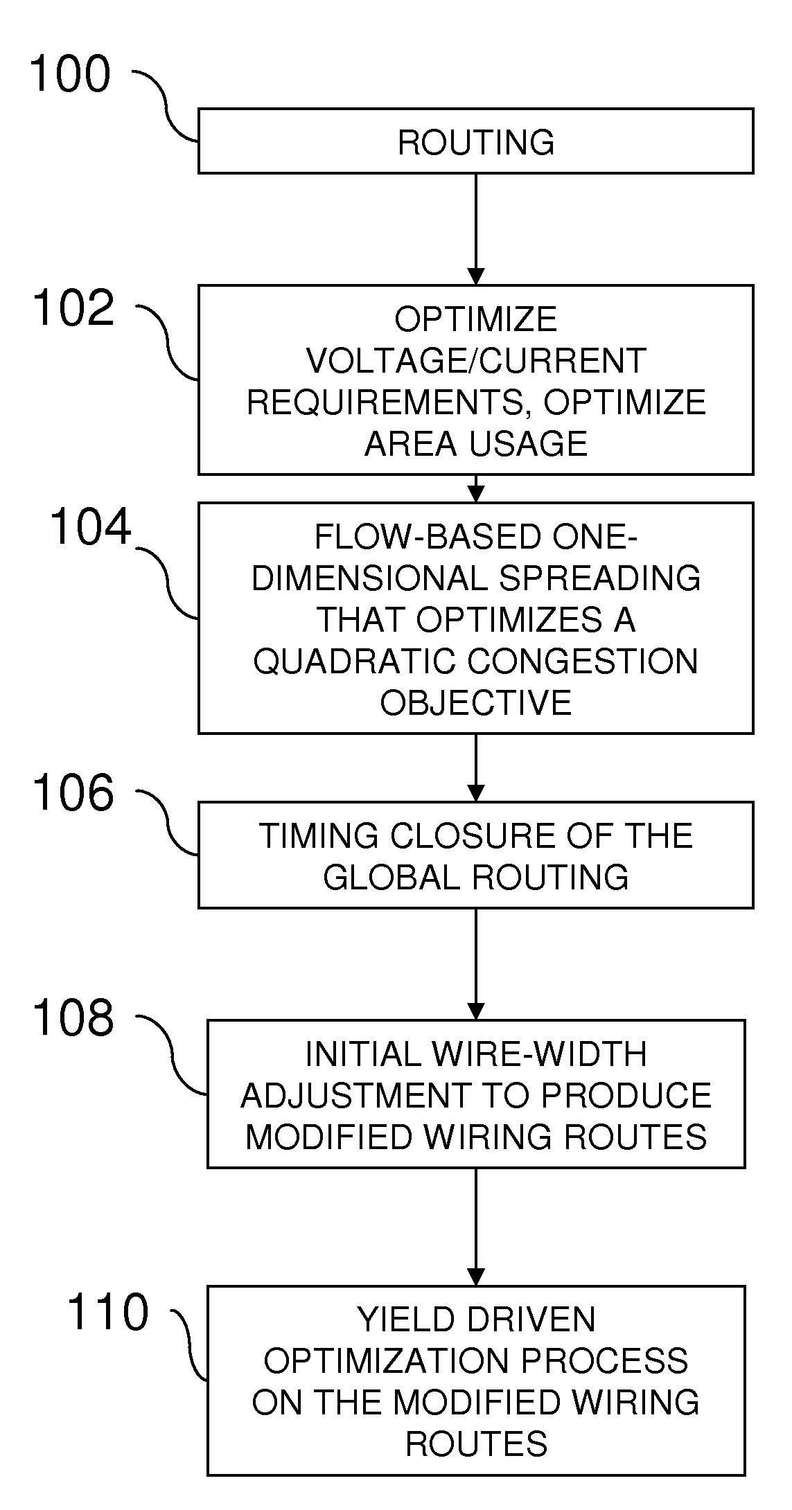
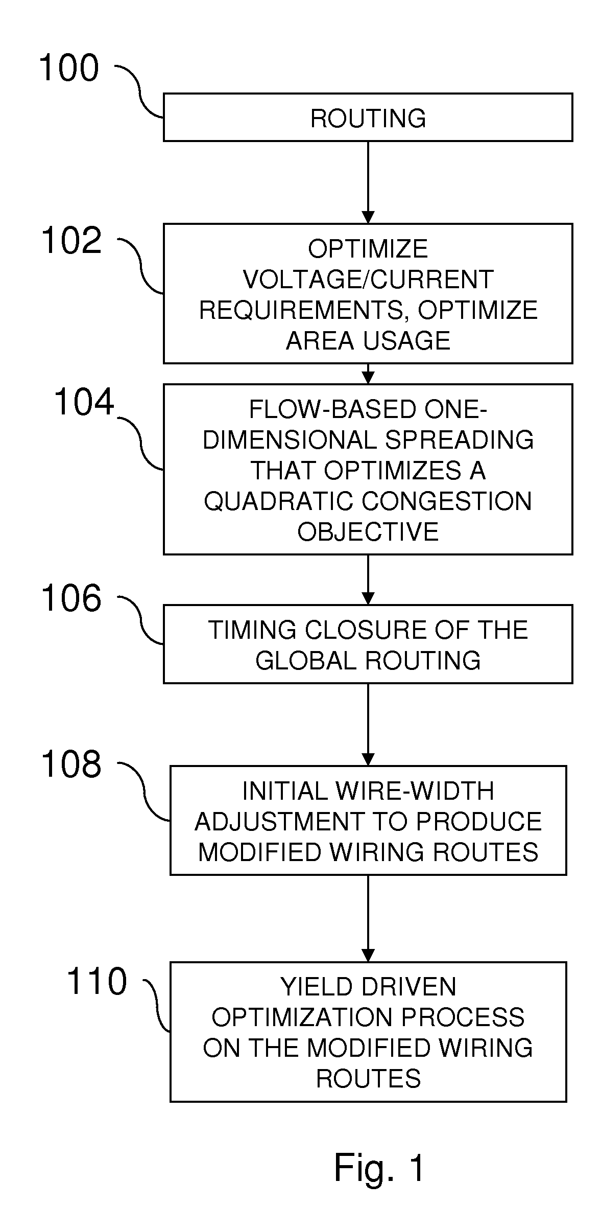
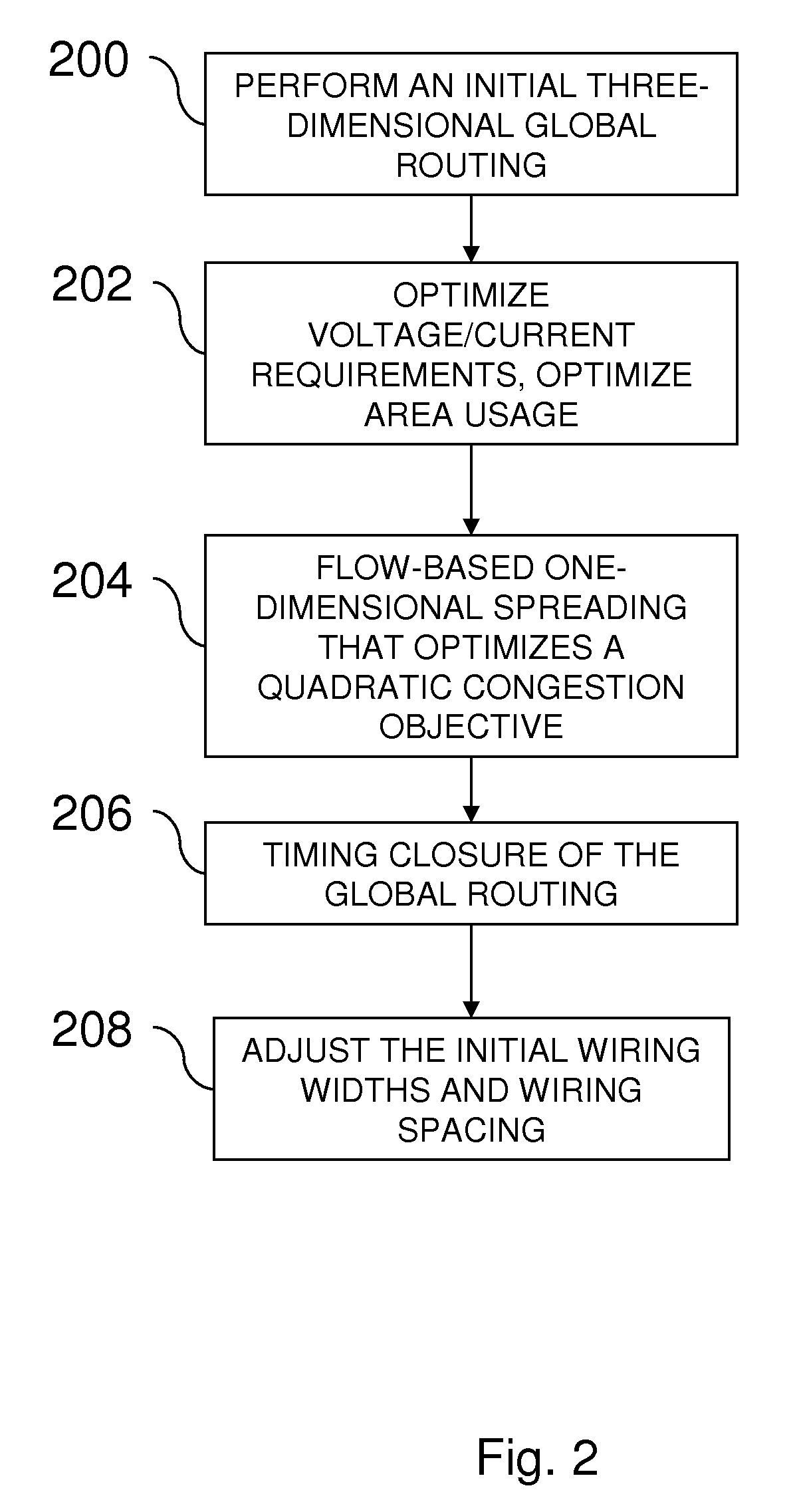
[0008]When making the post-routing wiring width adjustments, the method creates modified wiring widths and modified spacing between wires. The making of the post-routing wiring width and length adjustments balances trade-offs between wire widths and wire spacings. The making of the post-routing wiring width and length adjustments avoids altering relative locations of the wiring routes.
[0013]More specifically, the following describes a global routing method that optimizes wire widths and spacings for yield, while accomplishing the tasks of timing closure and signal integrity. In a post-routing optimization step, the invention derives cost functions associated with wire widths, lengths and spacings and forms constraints to represent design rules and connectivity. The invention then optimizes while maintaining existing topological relationships (for example, vias can be moved without re-routing wires). The result is a set of wires with adjusted widths and spacings such that the overall critical area of the design is reduced. The post-routing optimization step can be used on its own, without the global routing solution. Thus, it allows for some yield optimization, regardless of the routing technology that might have been used to route the design.

Problems solved by technology

Wire spreading (increasing the space between individual wires) reduces the likelihood of spot defects falling between wires and producing shorts; wire-length minimization reduces both the likelihood of spot defects that cause opens and those that cause shorts; and redundant via insertion reduces the likelihood that blocked vias will result in fatal (yield reducing) defects.

Method used


Image

  • Method for IC wiring yield optimization, including wire widening during and after routing
  • Method for IC wiring yield optimization, including wire widening during and after routing
  • Method for IC wiring yield optimization, including wire widening during and after routing

Examples


Embodiment Construction

[0020]The present invention and the various features and advantageous details thereof are explained more fully with reference to the nonlimiting embodiments that are illustrated in the accompanying drawings and detailed in the following description. It should be noted that the features illustrated in the drawings are not necessarily drawn to scale. Descriptions of well-known components and processing techniques are omitted so as to not unnecessarily obscure the present invention. The examples used herein are intended merely to facilitate an understanding of ways in which the invention may be practiced and to further enable those of skill in the art to practice the invention. Accordingly, the examples should not be construed as limiting the scope of the invention.

[0021]As mentioned above, there is a clear need for more effective techniques to reduce the likelihood of opens (unintentionally broken circuits). The embodiments herein modify the wire widths in a layout to achieve a reduct...


PUM


Abstract

Disclosed are embodiments of a method, service, and computer program product for performing yield-aware IC routing for a design. The method performs an initial global routing which satisfies wiring congestion constraints. Next, the method performs wire spreading and wire widening on the global route, layer by layer, based on, for example, a quadratic congestion optimization. Following this, timing closure is performed on the global route using results of the wire spreading and wire widening. Post-routing wiring width and wire spreading adjustments are made using the critical area yield model. In addition, the method allows for the optimization of already-routed data.

Description

CROSS-REFERENCE TO RELATED APPLICATIONS[0001]This application is a divisional of U.S. application Ser. No. 11 / 275,076 filed Dec. 8, 2005, the complete disclosure of which, in its entirety, is herein incorporated by reference.BACKGROUND OF THE INVENTION[0002]1. Field of the Invention[0003]Embodiments herein present a method, service, computer program product, etc. for performing yield-aware IC routing for a design.[0004]2. Description of the Related Art[0005]Traditional methods for decreasing critical area (and so increasing random-defect yield) in the wiring layers of a VLSI (very large scale integration) layouts control wire spacing, reduce isolated via counts and reduce overall wire length, either during routing or as a post-routing step. Wire spreading (increasing the space between individual wires) reduces the likelihood of spot defects falling between wires and producing shorts; wire-length minimization reduces both the likelihood of spot defects that cause opens and those that...

Claims


Application Information

Patent Timeline
Patent Type & Authority Applications(United States)
IPC IPC(8): G06F17/50
CPCG06F17/5077G06F30/394
Inventor COHN, JOHN M.HIBBELER, JASON D.TELLEZ, GUSTAVO E.
Owner GLOBALFOUNDRIES INC
Learn More