
Radio communication apparatus and resending controlling method

a technology of radio communication apparatus and controlling method, which is applied in the field of radio communication apparatus and resending controlling method, can solve the problems that the effect of resending control cannot be so much obtained, and the probability of successful reception at the time of resending operation cannot be so much enhanced, so as to achieve the effect of improving significantly the synthesized gain

Active Publication Date: 2010-01-28
INTERDIGITAL PATENT HLDG INC
View PDF10 Cites 21 Cited by
  • Summary
  • Abstract
  • Description
  • Claims
  • Application Information

AI Technical Summary

Benefits of technology

[0034]According to the present invention, the radio communication apparatus and the resending controlling method, capable of improving significantly a synthesized gain in the resending operation by the relatively simple control when the resending control is applied at a time of execution of the transmission diversity using CDD can be provided.

Problems solved by technology

However, when the propagation state in the radio propagation paths was seldom changed in the resending operation from that in the transmission at the first time, an effect of the resending control cannot so much obtained in the above-mentioned situation.
As a result, such a problem existed that a synthesized gain obtained when the resending signals are composed by the resending control is not so much improved by employing CDD, and thus a probability of successful reception at a time of resending operation cannot be so much enhanced.

Method used


Image

  • Radio communication apparatus and resending controlling method
  • Radio communication apparatus and resending controlling method
  • Radio communication apparatus and resending controlling method

Examples


first embodiment

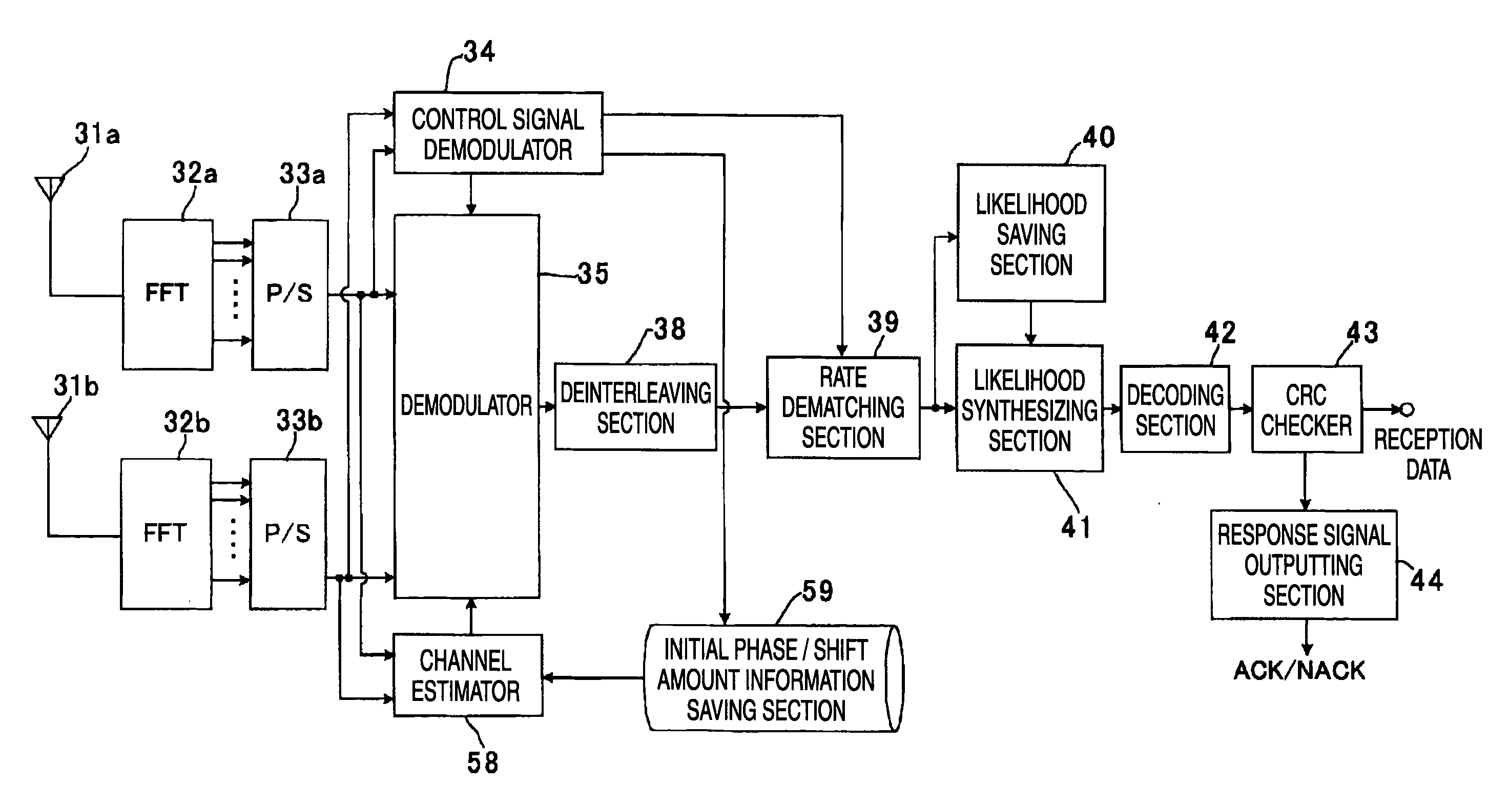
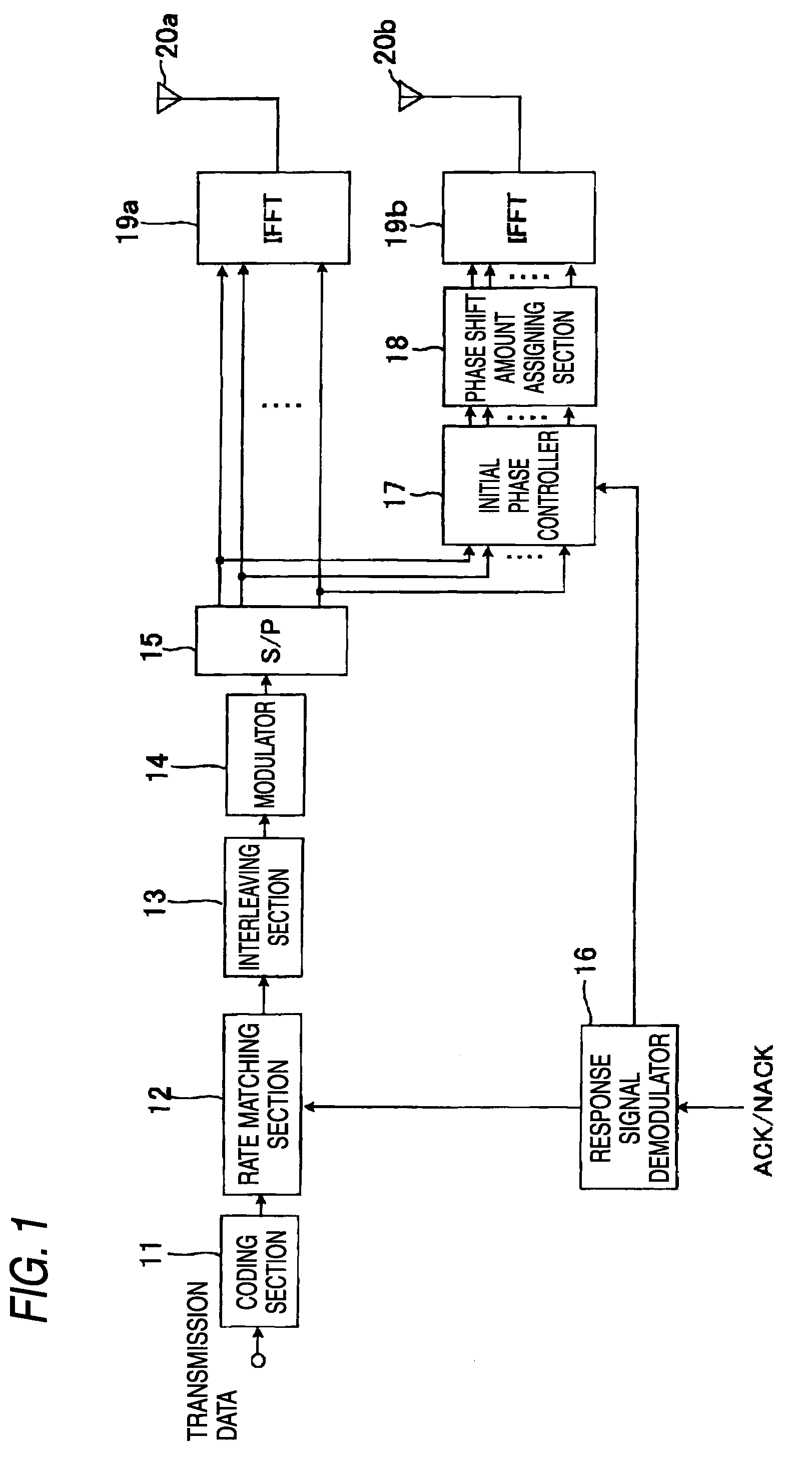
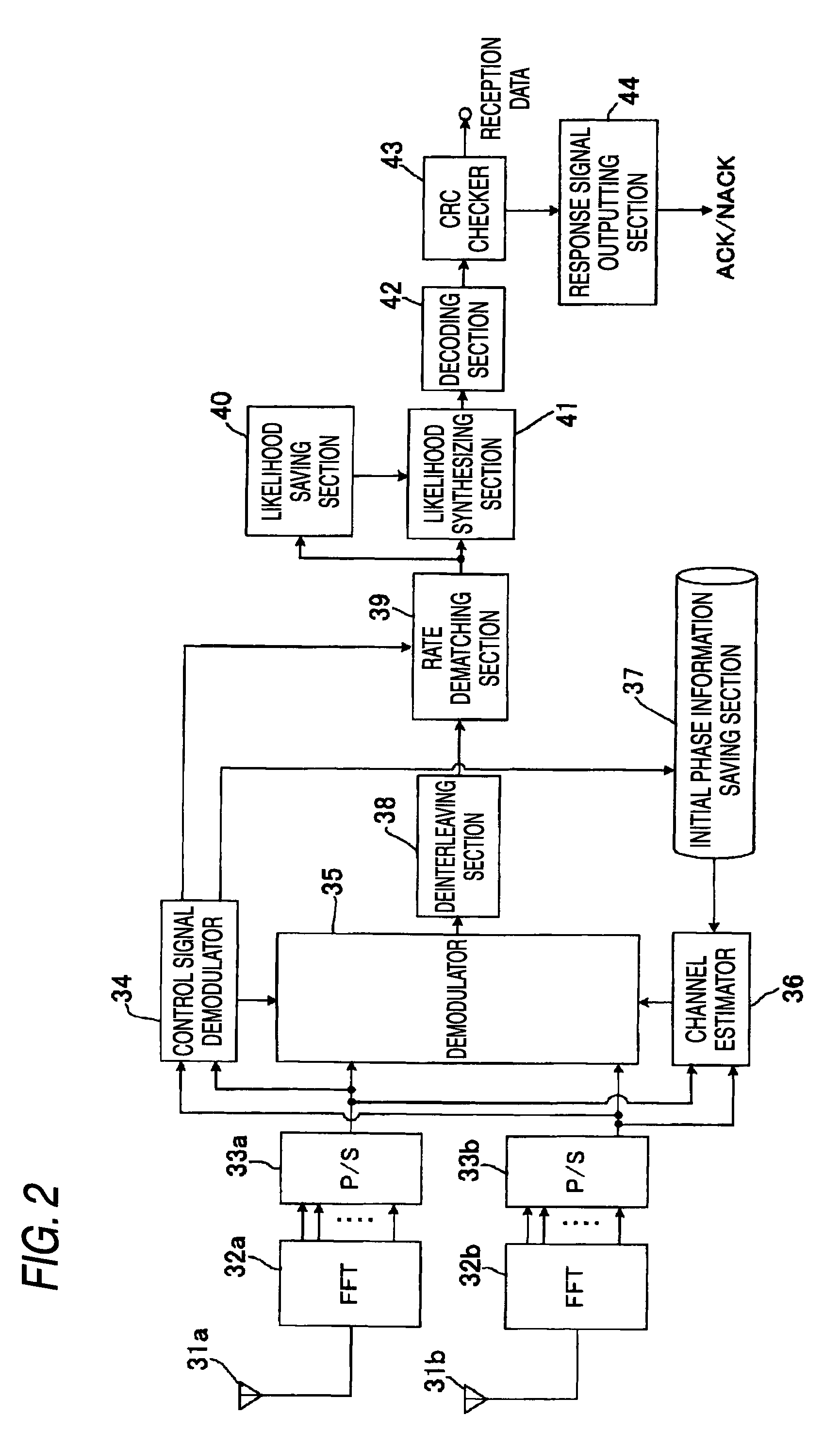
[0080]FIG. 1 is a block diagram showing a configuration of principal sections of a transmitting station employed in a first embodiment of the present invention. FIG. 2 is a block diagram showing a configuration of principal sections of a receiving station employed in the first embodiment of the present invention.

[0081]In the present embodiment, such a case is assumed that radio communication is held between the transmitting station shown in FIG. 1 and the receiving station shown in FIG. 2 by a radio wave. For example, such a situation is assumed that the transmitting station (transmitting equipment) shown in FIG. 1 is applied as a radio communication base station equipment (radio base station) of the cellular system, which provides a communication service of a mobile communication such as a cellular phone, or the like, and also the receiving station (receiving equipment) shown in FIG. 2 is applied as a user equipment (UE) serving as a radio communication mobile station equipment suc...

second embodiment

[0132]FIG. 9 is a block diagram showing a configuration of principal sections of a transmitting station employed in a second embodiment of the present invention. FIG. 10 is a block diagram showing a configuration of principal sections of a receiving station employed in the second embodiment of the present invention.

[0133]The second embodiment is an example in which a part of the first embodiment is varied. Here, in the second embodiment, the same reference symbols are affixed to the similar elements to those in the first embodiment, and their detailed explanation will be omitted herein.

[0134]The transmitting station shown in FIG. 9 is equipped with an antenna mapping section 21 as a new constituent element in contrast to the configuration in FIG. 1. The antenna mapping section 21 fulfills a function of a antenna mapping controller. The antenna mapping section 21 is provided between an output of the serial / parallel converter 15 and an input of the inverse Fourier transformer 19a and ...

third embodiment

[0150]FIG. 13 is a block diagram showing a configuration of principal sections of a transmitting station employed in a third embodiment of the present invention. FIG. 14 is a block diagram showing a configuration of principal sections of a receiving station employed in the third embodiment of the present invention.

[0151]The third embodiment is an example in which a part of the first embodiment is varied. Here, in the third embodiment, the same reference symbols are affixed to the similar elements to those in the first embodiment, and their detailed explanation will be omitted herein.

[0152]In the transmitting station shown in FIG. 13, an operation of a phase shift amount assigning section 23 is different slightly from that in the configuration shown in FIG. 1. This phase shift amount assigning section 23 fulfills a function of the phase shift amount controller. Also, configurations and operations of remaining constituent elements are similar to those of the transmitting station shown...


PUM


Abstract

A synthesized gain in a resending operation can be improved significantly by relatively simple control when resending control is applied upon executing of a transmission diversity using CDD. A radio communication apparatus equipped with a plurality of antennas and for performing communication by MIMO, includes a phase shift amount assigning section 18 for executing a CDD process to assign a cyclic phase shift to a transmission signal on a frequency axis, a response signal demodulator 16 for demodulating ACK / NACK received from a destination station, and outputting control information about a resending operation when NACK is received and a reception is failed, and an initial phase controller 17 for setting an offset to a phase shift at a time of CDD process in response to a number of transmission times in resending control such that a predetermined offset, which is produced by adding a phase difference from a signal transmitted from other antenna to the phase shift, is assigned to a signal transmitted from the antenna over a full frequency band, wherein a frequency characteristic of a radio propagation path at a time of resending is changed every time of transmission times.

Description

TECHNICAL FIELD[0001]The present invention relates to a radio communication apparatus and a resending controlling method, which are applicable to a radio communication system employing MIMO (Multi Input Multi Output).BACKGROUND ART[0002]In the most up-to-date radio communication system used in a cellular system for mobile communication such as a cellular phone, or the like, for example, a plurality of antennas are provided to each radio communication station by employing MIMO, and also a study of introduction of CDD (Cyclic Delay Diversity) that is one type of DD (Delay Diversity) as a transmission diversity is advancing.[0003]In the delay diversity, a transmitting station transmits the same signals from a plurality of antennas and such signals are controlled such that a sufficient time difference (delay) in signal is produced among a plurality of antennas respectively. Accordingly, even when an interval between a plurality of antennas is small, a sufficient difference (time differe...

Claims


Application Information

Patent Timeline
Patent Type & Authority Applications(United States)
IPC IPC(8): H04B7/02H04J99/00
CPCH04B7/04H04L1/1867H04B7/068
Inventor HOSHINO, MASAYUKIHIRAMATSU, KATSUHIKO
Owner INTERDIGITAL PATENT HLDG INC
Learn More