
Display Device

Active Publication Date: 2010-01-28
PANASONIC LIQUID CRYSTAL DISPLAY CO LTD +1
View PDF14 Cites 46 Cited by
  • Summary
  • Abstract
  • Description
  • Claims
  • Application Information

AI Technical Summary

Benefits of technology

[0012]Further, the pad part of the each of the plurality of X electrodes may extend to a vicinity of the thin line part of one of the plurality of X electrodes adjacent to the each of the plurality of X electrodes. In plan view, in a shape of the pad part of the each of the plurality of X electrodes, an area may be smallest in the vicinity of the thin line part of the adjacent one of the plurality of X electrodes and an area may be largest in the vicinity of the thin line part of the each of the plurality of X electrodes. An area of the pad part may be reduced from the vicinity of the thin line part of the each of the plurality of X electrodes to the vicinity of the thin line part of the adjacent one of the plurality of X electrodes. Thus, even when an electrode interval of the plurality of X electrodes is larger than a contact surface of a touch operation, a touch coordinate position may be calculated based on a ratio of detected capacity components of the adjacent X electrodes, thereby making it possible to perform highly accurate position detection with a small number of electrodes.
[0013]Further, the one of the plurality of Z electrodes and the one Z electrode is formed so as to overlap both the plurality of X electrodes and the plurality of Y electrodes which are adjacent to each other, whereby a capacity change may be detected at the adjacent one of the plurality of Y electrodes through the one of the plurality of Z electrodes and the one Z electrode even when there is a contact surface of the touch above the plurality of X electrodes, and a capacity change may be detected at the adjacent one of the plurality of X electrodes through the one of the plurality of Z electrodes and the one Z electrode even when there is a contact surface of the touch above the plurality of Y electrodes. Thus, input coordinates may be detected on the entire surface of the touch panel. Simultaneously, the number of Y electrodes may be reduced.
[0014]According to the present invention, contriving shapes and an arrangement of the electrodes of the touch panel enables position detection with a smaller number of electrodes and with higher accuracy compared with the conventional case.

Problems solved by technology

In the resistance film method, a touch position is detected by mechanical contact of the resistance film, thereby leading to possible deterioration or breakage of the resistance film.
However, in the electrostatic capacity coupling method, there is no mechanical contact such as contact of a detection electrode with another electrode.
Even when the detection electrode is deteriorated to change a resistance value as physical characteristics, its influence on capacity detection is limited.
If a contact surface of the stylus has a diameter of 1 mm, and detection electrodes are prepared by using this size as an electrode interval, on the other hand, the total number of electrodes is 139, which indicates an increase of about six times. The increased number of electrodes causes an increase in frame area necessary for laying wiring lines in the input processing unit, and an increase in number of signal connections with a control circuit, consequently lowering reliability against shock and the like.
Further, a circuit area increases due to an increase in number of terminals of the input processing unit, thereby leading to a fear of a cost increase.

Method used


Image

  • Display Device
  • Display Device
  • Display Device

Examples


first embodiment

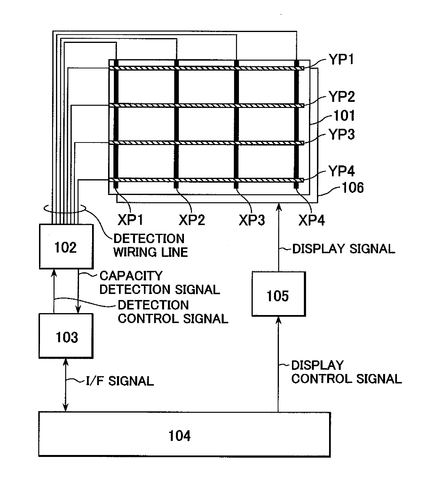
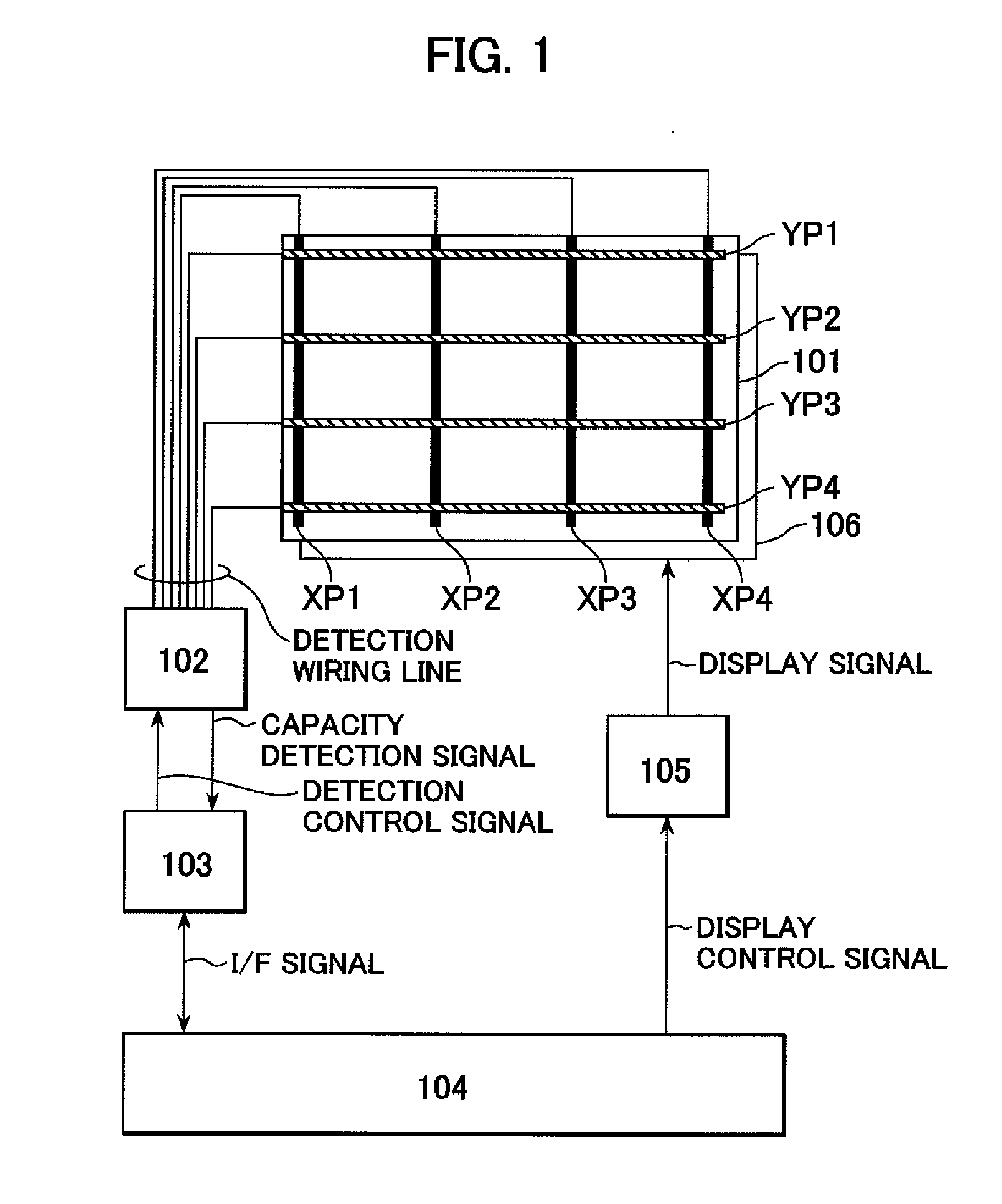
[0051]FIG. 1 illustrates configurations of an input device (hereinafter, referred to as a touch panel) and a display device including the input device.

[0052]In FIG. 1, a reference numeral 101 denotes a touch panel according to a first embodiment. The touch panel 101 includes capacity detection X and Y electrodes XP and YP. For example, four (XP1 to XP4) X electrodes and four (YP1 to YP4) Y electrodes are illustrated in this case. It should be noted that the numbers of electrodes are not limited thereto. The touch panel 101 is installed in a front face of a display device 106. Thus, when a user views an image displayed on the display device, a transmittance of the touch panel is preferably high because the displayed image needs to pass through the touch panel. The X and Y electrodes of the touch panel 101 are connected to a capacity detection unit 102 via detection wiring lines. The capacity detection unit 102 is controlled based on a detection control signal output from a control ca...

second embodiment

[0092]Next, a touch panel according to a second embodiment of the present invention is described. The touch panel according to the second embodiment of the present invention is different in shape of the Z electrode from the touch panel according to the first embodiment of the present invention. Hence, components other than the Z electrode are similar to those of the above-mentioned first embodiment of the present invention.

[0093]Referring to FIGS. 19 and 20, description is made of the shape of the Z electrode included in the touch panel according to the second embodiment of the present invention. As illustrated in FIG. 19, the Z electrode ZP is not divided by a slit, but has a solid electrode shape (shape in which the substantially entire display screen of the touch panel is covered). The Z electrode ZP having the solid electrode shape is also in an electrically floating state. FIG. 20 is a sectional view taken from points A to B in this case. The Z electrode ZP having the solid ele...


PUM


Abstract

A display device having an electrostatic capacity touch panel includes: X electrodes XP and Y electrodes YP which intersect each other via a first insulating layer; and a plurality of Z electrodes disposed in a floating state via a second insulating layer. For the second insulating layer, a material such as an elastic insulating material which changes in thickness by pressing of touch is used. The Z electrode is disposed so as to overlap both one of the X electrodes and one of the Y electrodes. A pad part of the X electrode has a largest area in the vicinity of a thin line part of the X electrode, and a smallest area in the vicinity of the thin line part of the adjacent X electrode. An area of the pad part is reduced as the pad part departs from the thin line part of the X electrode.

Description

CROSS-REFERENCE TO RELATED APPLICATION[0001]The present application claims priority from Japanese application JP 2008-191868 filed on Jul. 25, 2008, the content of which is hereby incorporated by reference into this application.BACKGROUND OF THE INVENTION[0002]1. Field of the Invention[0003]The present invention relates to a display device including the input device for inputting coordinates to a screen, and more particularly, to a display device which includes an input device of a capacity coupling type and which is suitable for achieving high coordinate detection accuracy.[0004]2. Description of the Related Art[0005]A display device including an input device (hereinafter, also referred to as “touch sensor” or “touch panel”) having an on-screen input function of inputting information to a display screen by a touch operation (contact and press operation, hereinafter, simply referred to as “touch”) with a user's finger or the like is used for a mobile electronic device such as a PDA ...

Claims


Application Information

Patent Timeline
IPC IPC(8): G06F3/041
CPCG06F3/044G06F3/0445G06F3/0446G06F3/0447G06F3/0412G06F3/0448
Inventor MAMBA, NORIOFURUHASHI, TSUTOMUANNO, KOUICHI
Owner PANASONIC LIQUID CRYSTAL DISPLAY CO LTD
Learn More