
Wheel tractor scraper rear wheel drive assist and method of operation

a technology of rear wheel drive and wheel tractor, which is applied in the direction of tilling equipment, transportation items, agricultural machines, etc., can solve the problems of limited tractor scraper operation, affecting the operation of the second machine, and the traction conditions of the work si

Active Publication Date: 2010-01-28
CATERPILLAR INC
View PDF15 Cites 25 Cited by
  • Summary
  • Abstract
  • Description
  • Claims
  • Application Information

AI Technical Summary

Benefits of technology

[0008]In one aspect, the present disclosure provides a wheel tractor scraper having a tractor portion that includes a power source drivingly connected to at least one front wheel of the scraper, and a scraper portion pivotally connected to the tractor portion, the scraper portion having the bowl and at least one rear wheel. A work tool is also connected to the rear scraper portion and configured to load the bowl, the work tool being powered by a work tool pump that is fluidly connected to a fluid operated work tool motor. The rear wheel drive ass

Problems solved by technology

One of the limiting factors associated with wheel tractor scraper operations are the traction conditions of the work site.
Tractor scraper operations can be limited, for example, by the type of material, geographic location, and seasonal conditions of the work site.
However, the option of a second machine is not always possible, and this increases operating costs.
Further, this does not address concerns of the tractor scraper becoming stuck during the remainder of the work cycle.
However, this requires an additional and dedicated fluid pump, fluid lines, and other components that significantly add to overall vehicle complexity and cost.

Method used


Image

  • Wheel tractor scraper rear wheel drive assist and method of operation
  • Wheel tractor scraper rear wheel drive assist and method of operation
  • Wheel tractor scraper rear wheel drive assist and method of operation

Examples


Embodiment Construction

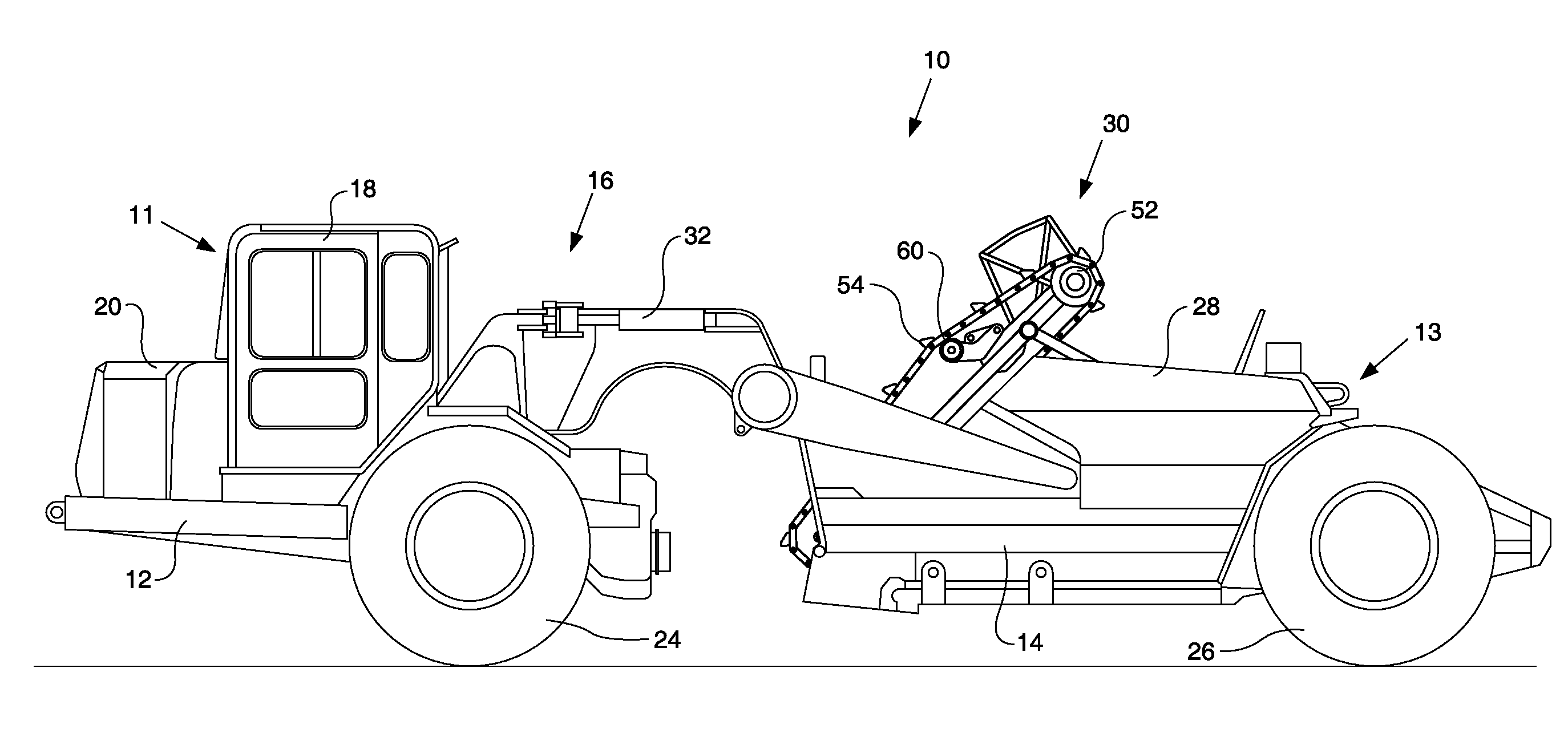
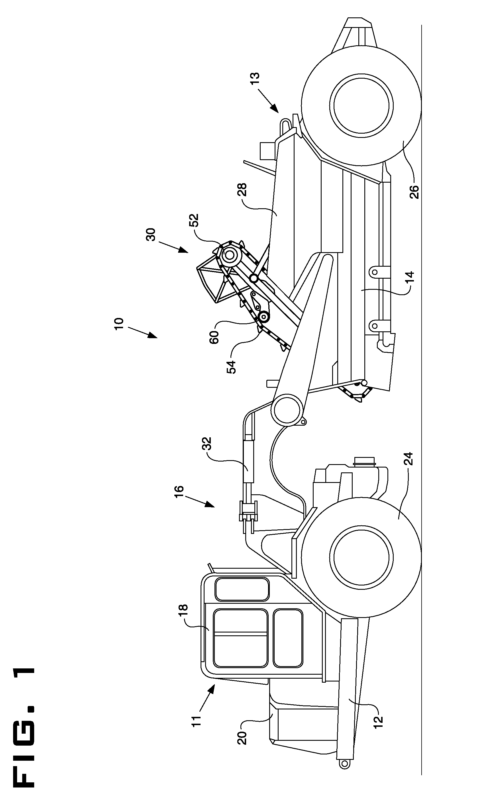
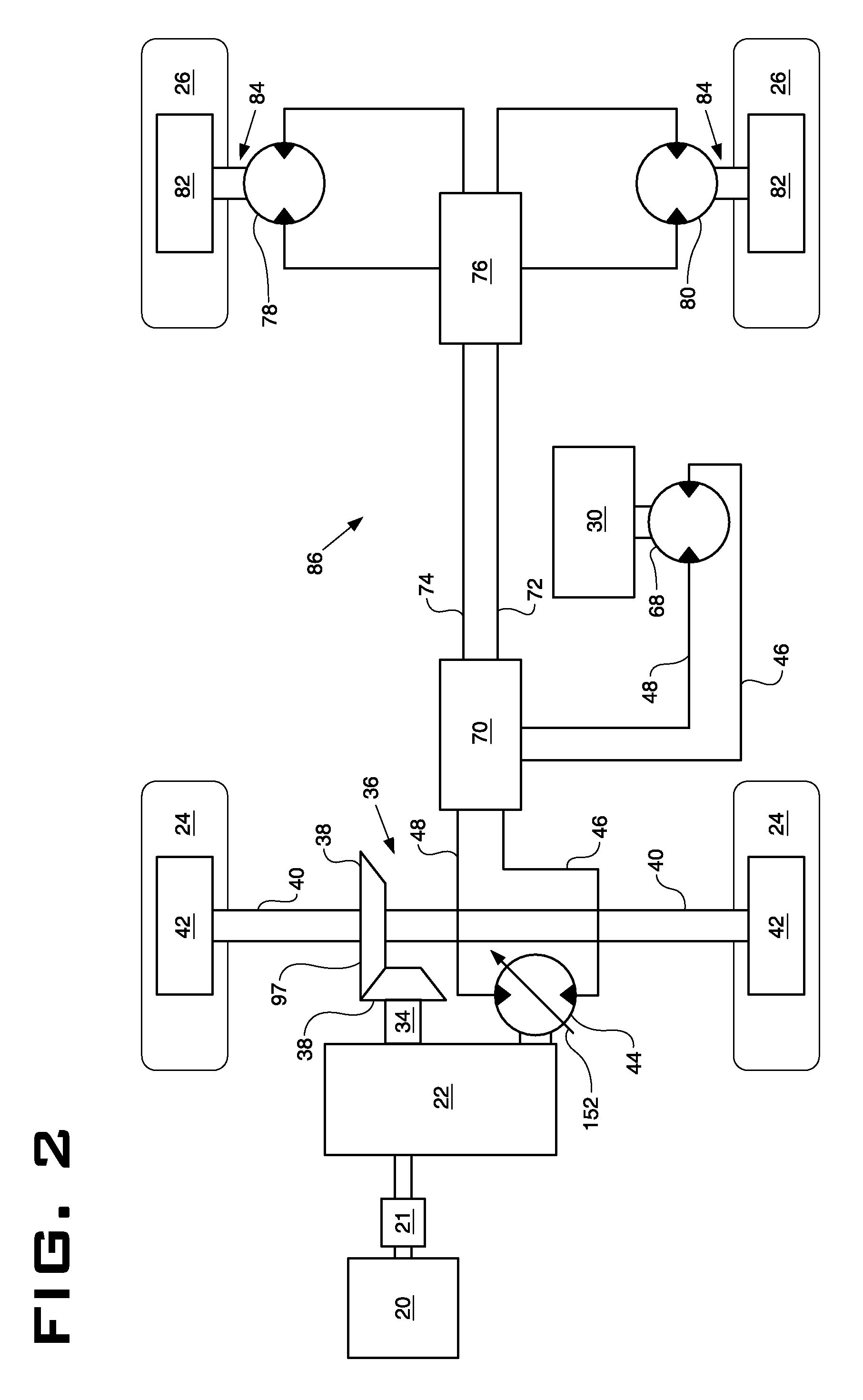
[0020]FIG. 1 illustrates an elevating wheel tractor scraper 10 having a tractor portion 11, with a front frame section 12, and a scraper portion 13, with a rear frame section 14, that are pivotally coupled through articulation hitch 16. Steering may be provided by steering cylinders 32 (one shown) mounted between the tractor portion 11 and scraper portion 13 on opposing sides of the machine. The front frame section 12 supports a cooling system (not shown) and power source 20, the power source 20 operatively connected through a transmission 22 (FIG. 2) to drive front wheels 24 for primary propulsion of the scraper 10. The front frame section 12 may also support an operator station 18 for primary control of the scraper 10 during ordinary operations.

[0021]The rear frame section 14 may support the bowl 28 and rear wheels 26. The bowl 28 may also include a fluid powered work tool 30, such as an elevator 52 (shown), auger, conveyor, or spade, to facilitate penetration and / or loading of th...


PUM


Abstract

A wheel tractor scraper having a rear wheel drive assist, the wheel tractor scraper includes a tractor portion pivotally coupled to a rear scraper portion, the rear scraper portion having a bowl for hauling material and a fluid powered work tool configured to assist in loading the bowl, the work tool powered by a fluid pump connected to a fluid operated work tool motor. The rear wheel drive assist includes a fluid operated drive motor coupled to the rear wheels of the machine, a diverter valve having a first position at which fluid flow is delivered from the pump to the work tool motor and a second position at which fluid flow is delivered from the pump to the drive motor, and a controller being configured to control the diverter valve to engage the rear wheel drive assist. The machine may be operated by engaging the pump and work tool motor, and then actuating the diverter valve to the second position to divert flow from the work tool motor to the drive motor.

Description

TECHNICAL FIELD [0001]This disclosure relates generally to the art of earth moving equipment and particularly to a fluid operated rear wheel drive assist for a wheel tractor scraper.BACKGROUND [0002]The wheel tractor scraper is a machine employed in various industries, such as agriculture, construction and mining to load, haul, eject and spread layers of earth. Such machines are particularly suited for applications, for example, in roadway construction and site preparation, where material needs to be removed or added while creating or maintaining grade and hauling occurs over moderate distances, e.g. under one mile. Conventional wheel tractor scrapers typically include a tractor portion having a forward frame member that supports the operator station and a power source operatively coupled to the driven wheels of the machine. An articulated joint couples the tractor portion to the rear scraper portion, the scraper portion having a rear frame member that supports both a bowl for colle...

Claims


Application Information

Patent Timeline
IPC IPC(8): E02F9/20
CPCB60K17/356E02F3/6481E02F9/2253E02F3/655E02F3/651
Inventor CARLTON, DOUGLAS J.DANIEL, STEVEN A.SERGISON, DANIEL P.STONE, ROBERT E.STORER, CROWIN E.THOMSON, NORVAL P.WEIER, TODD M.
Owner CATERPILLAR INC
Learn More