Eureka AIR delivers breakthrough ideas for toughest innovation challenges, trusted by R&D personnel around the world.

Fender assembly for wheel tractor-scrapers

Inactive Publication Date: 2015-12-10
CATERPILLAR INC
View PDF2 Cites 4 Cited by
  • Summary
  • Abstract
  • Description
  • Claims
  • Application Information

AI Technical Summary

Benefits of technology

The present patent describes a fender assembly for a machine. The assembly includes a primary fender and a secondary fender, which is connected to the primary fender and extends into a gap between the machine's frame and a tire. The secondary fender is made of a non-rigid material and is supported by an intermediate support assembly that provides a clearance between the fender and the tire. This design allows for easy removal of the secondary fender for cleaning or replacement. The technical effect of this design is to provide improved protection and prevention of damage to the tire by reducing the likelihood of debris buildup and impact.

Problems solved by technology

Construction machines, such as wheel tractor scrapers, that perform earthmoving operations are frequently subjected to rigorous operational conditions over considerably rugged terrains.
If left unattended, such a build-up generally accumulates in relatively large volumes within the clearance space.
A prolonged presence of build-up within such clearances may cause rusting, loss of paint, deterioration, and may even cause malfunction of certain components, accommodated and routed therein.
On several occasions, tire build-up is mixed with trash, sharp stones, hard gravel, and the like, which may severely deform the structure of the overlying fender.
Therefore, in due time, it is generally required to disassemble the fender assembly for repairs and replacement.
Therefore, present day removal practice is cumbersome, time consuming, and adds high downtime for machine operation.
Moreover, no solution is provided to ease a disassembly process of the quarter fender assembly from the frame of the truck.

Method used


Image

  • Fender assembly for wheel tractor-scrapers
  • Fender assembly for wheel tractor-scrapers
  • Fender assembly for wheel tractor-scrapers

Examples


Embodiment Construction

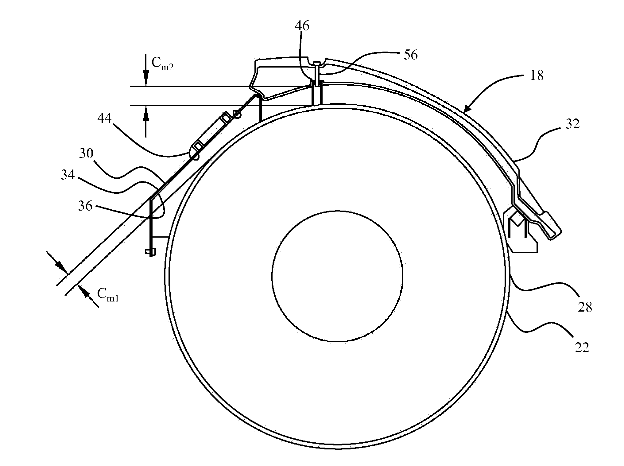
[0012]Referring to FIG. 1, there is shown an exemplary construction machine 10, which is referred to as a machine 10, hereinafter. The machine 10 is a wheeled tractor scraper or a wheeled scraper machine. However, an application of the present disclosure may be contemplated to other machines, such as wheeled excavators, wheeled loaders, and the like. An extension of this application to off-highway trucks, articulated trucks, haul trucks, large mining trucks (LMT), and other such wheeled machines, is also envisioned. The machine 10 may be electrically or mechanically operated. The machine 10 includes a scraper bowl 12, an operator cab 14, a frame 16, a fender assembly 18 connected to the frame 16, a hydraulic tank 20, and a tire 22, positioned underneath the fender assembly 18. The frame 16 also supports an engine compartment 24.

[0013]The scraper bowl 12 is used to carry payload material scraped from a ground surface 26. To facilitate such loading, the scraper bowl 12 may include a c...


PUM


Abstract

A fender assembly of a machine includes a frame and at least one tire. The fender assembly has a primary fender portion connected to the frame, and defines a first surface and a second surface. The first surface defines a gap with a first interface. The first fender portion is based on a rigid material. A secondary fender portion with an interfacial surface and tire-facing surface is contiguously connected with the primary fender portion, and extends into a gap between a second interface and the tire, while being restricted against the second interface. The secondary fender portion is based on a non-rigid material. An intermediate support assembly is connected to the tire-facing surface to support the secondary fender portion to the frame. The intermediate support assembly imparts a clearance with the tire to direct debris at the tire-facing surface, and is removable along a width and outwardly to the machine.

Description

TECHNICAL FIELD[0001]The present disclosure relates generally to a fender assembly for a machine. More specifically, the present disclosure relates to a laterally attachable fender assembly that defines sufficient clearances relative to the machine and a tire of the machine.BACKGROUND[0002]Construction machines, such as wheel tractor scrapers, that perform earthmoving operations are frequently subjected to rigorous operational conditions over considerably rugged terrains. Such terrains mostly include moist ground or sticky soil. As a tire of the construction machine rolls over such terrains, sticky soil may bond to the tire, in turn picking up the underlying debris and sticky clay. A continued tire roll causes a soil-debris mixture to be carried into a clearance space between the tire and a fender assembly of the construction machine. This leads to a situation commonly referred to as a mud build-up or simply a build-up on the tire. If left unattended, such a build-up generally accum...

Claims


Application Information

Patent Timeline
IPC IPC(8): B62D25/18
CPCB62D25/184B62D25/182B62D25/168
Inventor BOJAN, SRINIVASAN
Owner CATERPILLAR INC
Why Eureka
Eureka Blog
Learn More