
Handled baking dish

a baking dish and handle technology, applied in the field of cooking dishes, can solve the problems of increasing the susceptibility of cracking or uneven wear of bakeware, reducing the ability of bakeware to cook food evenly, and enclosing the baking dish with a wall, so as to reduce the likelihood of cracking or uneven wear, reduce the likelihood of user burns, and facilitate the transportation of baking dishes

Inactive Publication Date: 2010-01-28
HAEGER INDS
View PDF1 Cites 11 Cited by
  • Summary
  • Abstract
  • Description
  • Claims
  • Application Information

AI Technical Summary

Benefits of technology

[0012]The unitary design of the present invention provides a structure having a consistent thermal conductivity, which heats food evenly and decreases the likelihood of cracking or uneven wear. The handle design of the present invention eases the transport of the baking dish and decreases the likelihood that a user will be burned when removing the baking dish from an oven. The lack of enclosing walls in the design allows for convection heat to move freely around food during baking.

Problems solved by technology

Baking dishes with enclosing walls are not suitable for certain types of crusted foods that require heat to convect freely around all portions of the food.
This difference in material characteristics reduces the bakeware's ability to cook food evenly, and increases the bakeware's susceptibility to cracking or wearing unevenly.
Handles made from such materials increase the difficulty of moving a hot baking tray, and increase the risk of burning the hand or arm of a person removing the baking tray from an oven.

Method used


Image

  • Handled baking dish
  • Handled baking dish
  • Handled baking dish

Examples


first embodiment

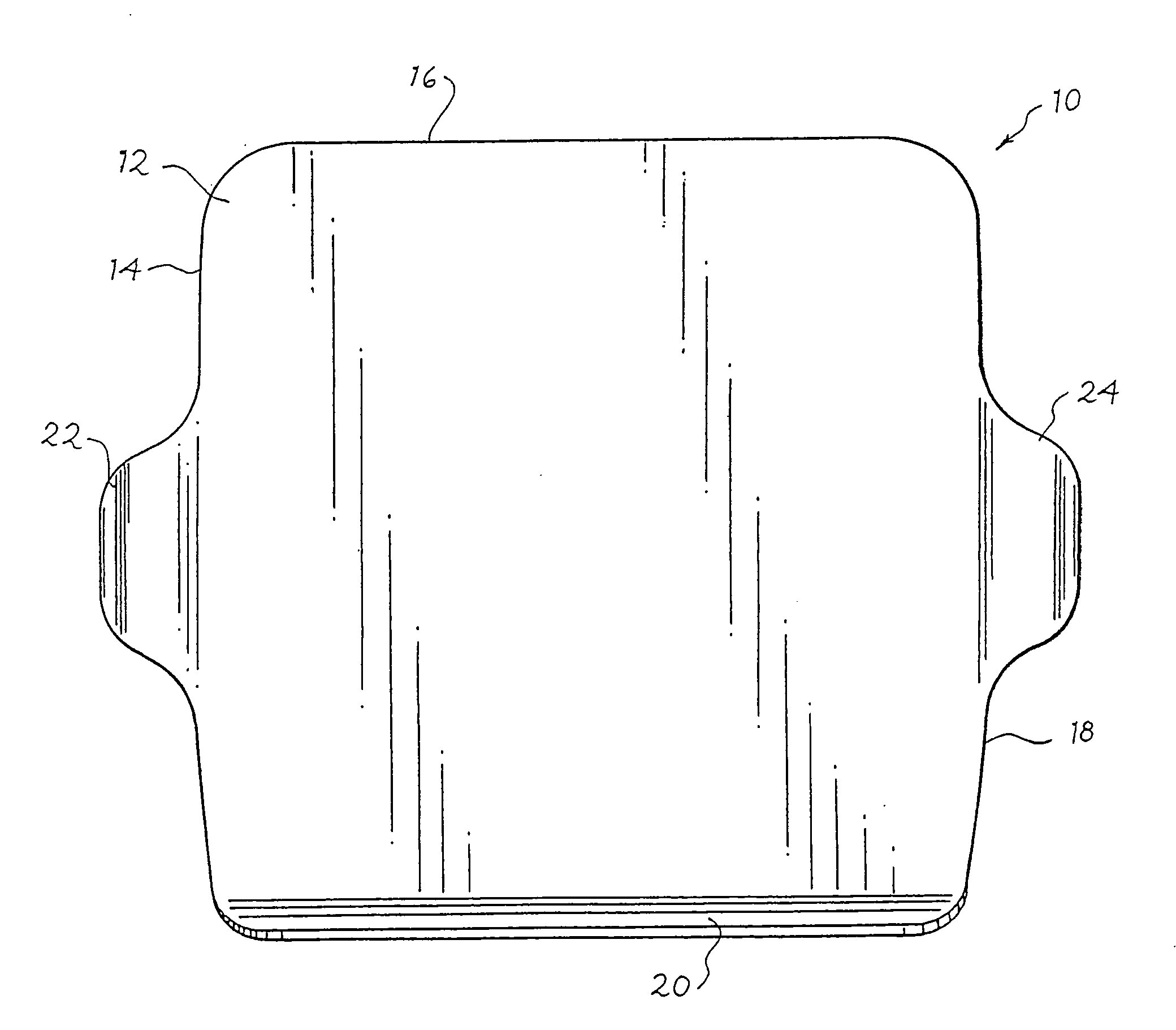
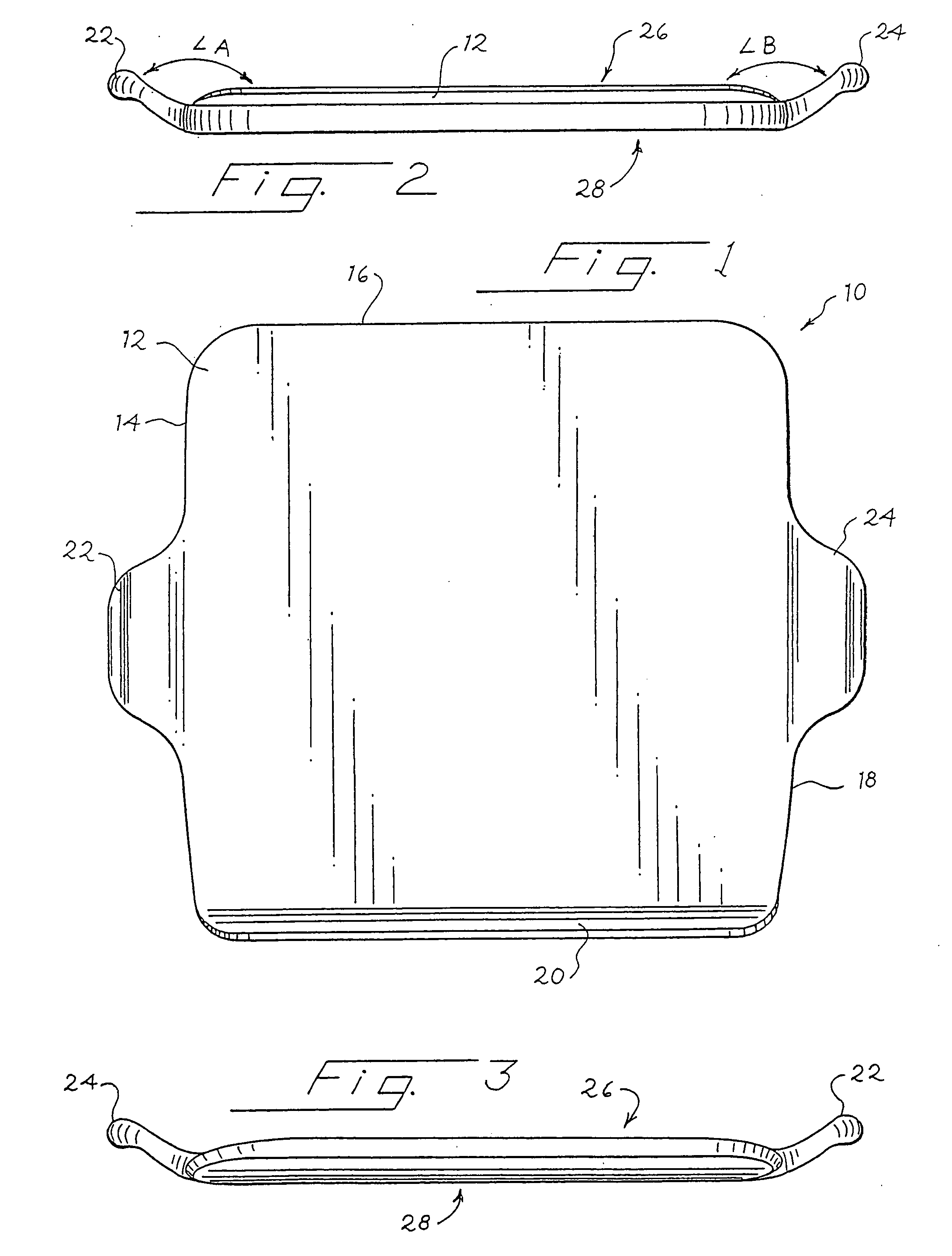
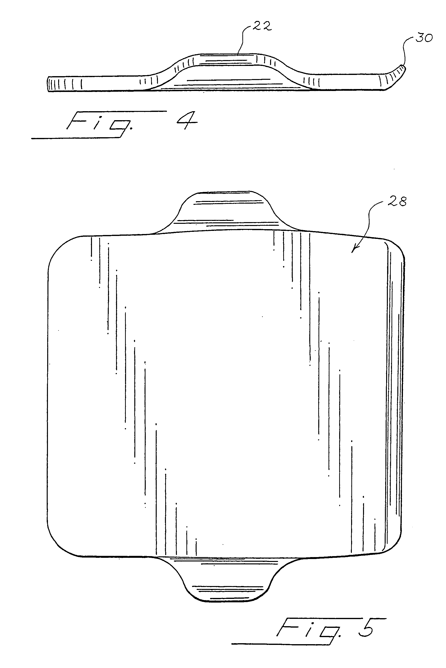
[0023]FIGS. 1 through 5 show a baking dish according to the present invention. As shown in FIG. 1, the baking dish 10 includes a flat tray 12 having a rectangular outer edge formed from four sides 14, 16, 18, 20. Flat tray 12 has a thickness of about ⅛ inch to about 2 inches, and preferably about ¼ inch to about ¾ inch. The thickness of the flat tray affects the thermal properties of the baking dish. Increasing the thickness of the flat tray increases the amount of time and heat needed to increase the temperature of the dish, and also increases the amount of time that the dish will retain heat after a heat source has been removed.

[0024]Extending from side 14 is first handle 22, and extending from side 18 is second handle 24. As shown in FIGS. 2 and 3, first handle 22 extends outward from one side of flat tray 12 and extends slightly above flat tray 12. Second handle 24 extends from an opposite side of flat tray 12 and extends slightly above flat tray 12. Handles 22,24 extend about 1...

second embodiment

[0030]FIGS. 6 through 9 show a baking dish according to the present invention. As shown in FIG. 6, the baking dish 110 includes a flat tray 112 having a circular outer circumference 114. Flat tray 112 has a thickness of about ⅛ inch to about 2 inches, and preferably about ¼ inch to about ¾ inch.

[0031]Extending from outer circumference 114 is first handle 122 and second handle 124. As shown in FIGS. 7 and 8, first handle 122 extends outward from one side of flat tray 112 and extends slightly above flat tray 112. Second handle 124 extends from an opposite side of flat tray 112 and extends slightly above flat tray 12. Handles 122,124 extend about 1 inch to about 5 inches outward and about ½ inch to about 4 inches upward from the outer edge of the flat tray 112. Handle 122 extends at obtuse angle C from flat tray 112, and handle 124 extends at obtuse angle D from flat tray 112. Handles 122, 124 are slightly curved and contain rounded end portions.

[0032]First handle 122 and second handle...


PUM


Abstract

The present invention is directed to a baking dish formed from a unitary non-metallic material. The baking dish comprises a flat tray portion of various shapes with handles extending from the sides of the flat tray portion. The handles are formed from the same non-metallic material that forms the other portions of the baking dish.

Description

FIELD OF THE INVENTION [0001]The present invention relates to cookware. In particular, the invention relates to improvements in baking dish design.BACKGROUND OF THE INVENTION [0002]Baking is a well known cooking process. During the baking process, the article to be baked is placed upon cookware and heated to the desired temperature for the desired amount of time.[0003]Two main cookware shape configurations are used in the baking process. The first type of configuration is a walled dish generally used to bake foods containing juices or liquids that need to be contained during the baking process. These types of dishes have enclosing walls around the entire perimeter of the dish that prevent food from flowing outside of the dish during baking. Baking dishes with enclosing walls are not suitable for certain types of crusted foods that require heat to convect freely around all portions of the food. Enclosing walls block the free flow of heat and prevent crust or bread portions of food fr...

Claims


Application Information

Patent Timeline
IPC IPC(8): A21B3/15
CPCA21B3/15
Inventor SNYDER, ROBERTBRADLEY, KEVIN
Owner HAEGER INDS
Learn More