
Method, system, and computer program product for a maintenance optimization model

a maintenance optimization and model technology, applied in the field of system and computer program product for maintenance optimization models, can solve the problems of not supporting the evaluation of systems and sub-systems as much, and the method cannot be taken,

Active Publication Date: 2010-01-21
AIRBUS OPERATIONS (SAS)
View PDF11 Cites 39 Cited by
  • Summary
  • Abstract
  • Description
  • Claims
  • Application Information

AI Technical Summary

Benefits of technology

The patent describes a method for developing a maintenance optimization model for a system, such as an aircraft system. This model takes into account future operational conditions and user expectations to predict the system's supportability performance. The method involves determining relevant outputs based on user expectations, inputs related to the system, and relationships between them. The model is designed based on the selected relevant output. The technical effect of this patent is to provide a technique for predicting the performance of a product in operation from the user's perspective, which can help improve system design and maintenance policies.

Problems solved by technology

Unfortunately these methods cannot be taken “as is” for an aircraft product evaluation.
These COO methods, however, consider primarily single parts Line Replaceable Units (LRUs) and do not support as much the evaluation of systems and sub-systems.
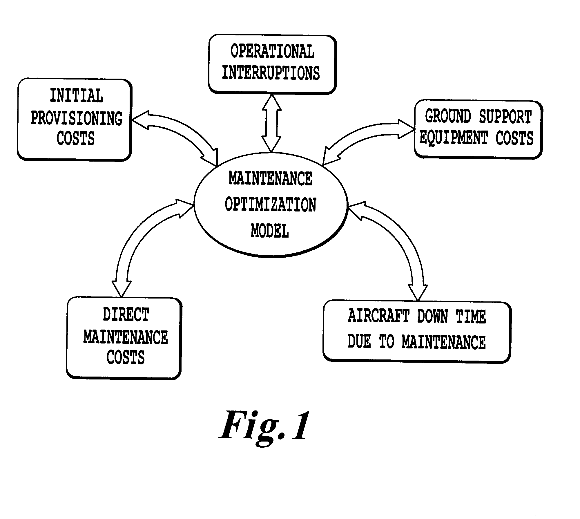
The cost elements considered in the DOCsys method of Scholz are:fuel costs caused by the system;Direct Maintenance Cost (DMC) caused by the system;capital costs caused by necessary spare parts on stock (spare holding costs); anddelay, cancellation, and diversion costs caused by an aircraft system.
However, in DOCSYS, fuel consumption is not in the supportability scope and several additional aspects are missing.

Method used


Image

  • Method, system, and computer program product for a maintenance optimization model
  • Method, system, and computer program product for a maintenance optimization model
  • Method, system, and computer program product for a maintenance optimization model

Examples


Embodiment Construction

[0032]Unless other wise defined, the following glossary applies hereinafter:[0033]AD Average Demand[0034]AT Administrative Time[0035]COO Cost Of Ownership[0036]DOC Direct Operating Cost[0037]DS Dispatch Status[0038]DMC Direct Maintenance Cost[0039]ED Estimated Demand[0040]ESS Essentiality[0041]FC Flight Cycle[0042]FH Flight Hours[0043]GDMC Guaranteed Direct Maintenance Cost[0044]GMTBUR Guaranteed Mean Time Between Failures[0045]GSE Ground Support Equipment[0046]I Scheduled interval length[0047]IFTB In-Flight Turn-Back[0048]ILS Integrated Logistic Support[0049]IOc Indirect Operating Cost[0050]IMC Indirect Maintenance Cost[0051]IP Initial Provisioning[0052]LCC Life Cycle Cost[0053]LRU Line Replaceable Unit[0054]LSC Life Support Cost[0055]LT Lead Time[0056]MAD Minimum Average Demand[0057]MEL Minimum Equipment List[0058]MMEL Master Minimum Equipment List[0059]MOM Maintenance Optimization Model[0060]MSG-3 Maintenance Steering Group-3[0061]SPT Shop Processing Time[0062]MTBD Mean Time Betw...


PUM


Abstract

A method of developing maintenance optimization model includes finding relevant criteria to drive the design towards operational performances at minimal cost for the end user, selecting inputs necessary to assess criteria selected, defining mathematical models to jointly drive the equipment / sub-system / system design and its support towards better supportability, and presenting the maintenance optimization model results to enable the exploration of the cause and effect relationships between design decisions and their operational and support impacts. The selected inputs may cover all the potential factors influencing the criteria values. The mathematical modeling can facilitate leveraging the intuitive “cause and effect” relationship between design and support, and affordability. The maintenance optimization model method, system, and computer program product provides a solid basis for the supportability evaluation of equipment / system / sub-system choices, particularly when integrated in a systematic way into the design process and used from the beginning of the development cycle.

Description

BACKGROUND OF THE INVENTION[0001]1. Field of the Invention[0002]The present invention relates to a method, system, and computer program product for a Maintenance Optimization Model (MOM), and more specifically to a method, system, and computer program product including a MOM driving design of a product, such as an aircraft, towards minimum operating cost while ensuring optimum availability for an end-user, such as an airline operating the aircraft.[0003]2. Description of the Related Art[0004]Design of certain products, such as an aircraft, has shifted its focus from the traditional design for performance to designing for affordability and quality. This paradigm shift calls for solutions that are beyond historical databases and demands the consideration of all aspects of the product's life cycle. An approach based on relations among reliability, availability, maintainability, and life cycle cost requirements can be more appropriate (see Jean-Jacques Dindeleux, Jacques J. Durand, Alst...

Claims


Application Information

Patent Timeline
Patent Type & Authority Applications(United States)
IPC IPC(8): G06Q10/00G06Q50/00G06G7/48G06F15/00
CPCG06Q10/0631G06Q10/00
Inventor LIENHARDT, BENEDICTE
Owner AIRBUS OPERATIONS (SAS)
Learn More