Bone screw retaining system

a bone screw and retaining system technology, applied in the field of surgical procedures, can solve the problems of compromising the load bearing and support capacity of the spine, affecting the implantation of known plating systems, and affecting the elasticity of the spin

Inactive Publication Date: 2010-01-21
ROBINSON JAMES C
View PDF4 Cites 114 Cited by
  • Summary
  • Abstract
  • Description
  • Claims
  • Application Information

AI Technical Summary

Problems solved by technology

As with any bony structure, the spine is subject to various pathologies that compromise its load bearing and support capabilities.
This requirement, that the bone screws do not loosen over time or back out from the plated, tends to complicate implantation of known plating systems.
Such bone screw retention systems generally ensure that the bone screws placed into the vertebrae through the plating system do not back out voluntarily from the plate, but typically do not adequately permit the removal of an associated bone screw when desired by the surgeon.
It is known that complications associated with any spi

Method used


Image

  • Bone screw retaining system
  • Bone screw retaining system
  • Bone screw retaining system

Examples


Embodiment Construction

[0039]The present invention can be understood more readily by reference to the following detailed description, examples, and claims, and their previous and following description. Before the present system, devices, and / or methods are disclosed and described, it is to be understood that this invention is not limited to the specific systems, devices, and / or methods disclosed unless otherwise specified, as such can, of course, vary. It is also to be understood that the terminology used herein is for the purpose of describing particular aspects only and is not intended to be limiting.

[0040]The following description of the invention is provided as an enabling teaching of the invention in its best, currently known embodiment. Those skilled in the relevant art will recognize that many changes can be made to the embodiments described, while still obtaining the beneficial results of the present invention. It will also be apparent that some of the desired benefits of the present invention can...


PUM


Abstract

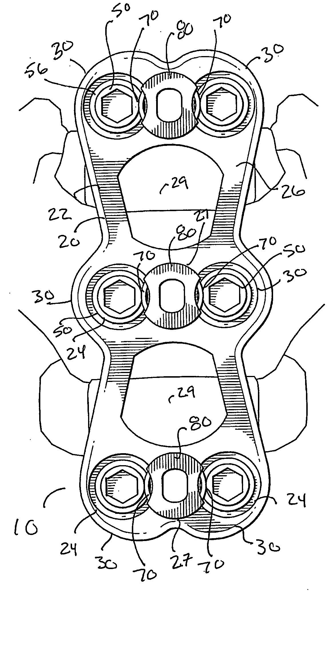
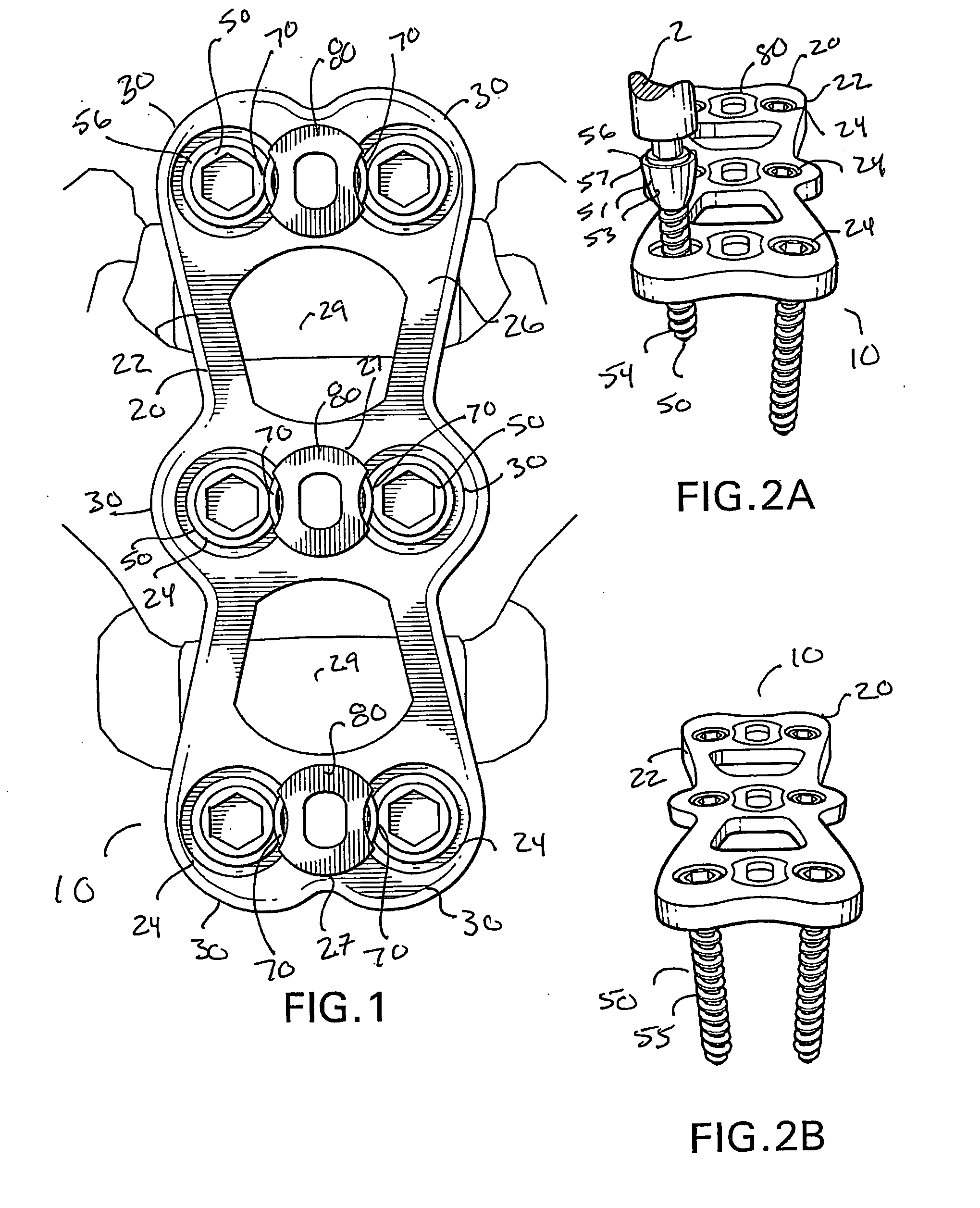
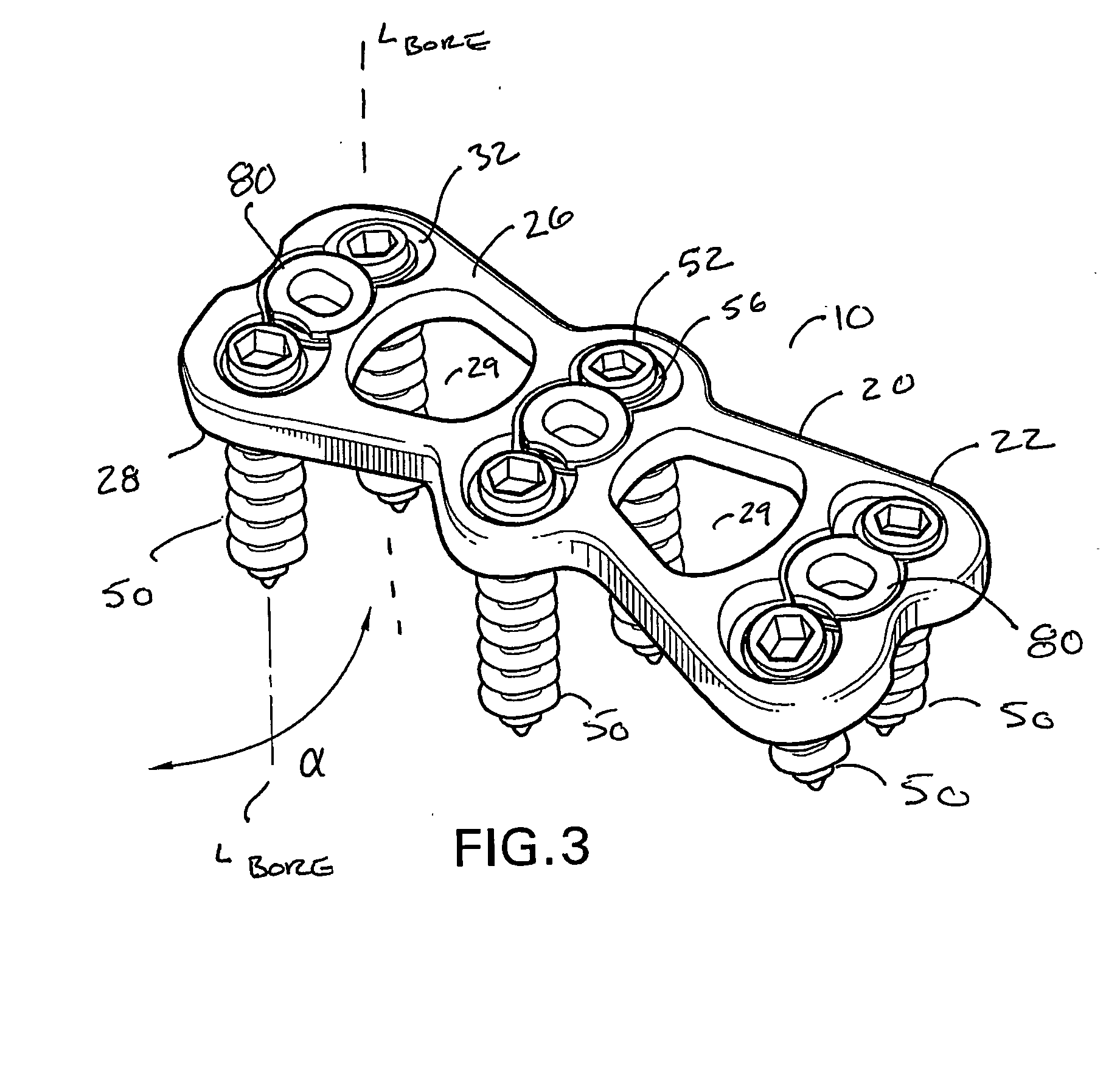
A bone screw retaining system including an implant adapted to be applied the anterior human cervical spine for contacting anterior aspects of at least two cervical vertebral bodies, the implant having a plate that defines a plurality of transversely extending bores that extend along a longitudinal axis between an anterior surface and a posterior surface, each bore being configured to receive a bone screw for engaging the plate to the cervical spine. An elastically deformable spring member positioned therein a cavity of the plate such that portions of the spring member can extend into a portion of an upper region of each of the bores of a pair of opposing bores, the spring member being movable between a first relaxed, expanded position and a second, compressed position. In the first relaxed position, at least a portion of the spring member extends outwardly substantially transverse to the longitudinal axis of the bore and into the upper region of the bore and, in the second position, portions of the spring member are medially biased away from the longitudinal axis of the bore toward the outer wall of upper region of the bore, which increases the effective inner diameter of the upper region of the bore.

Description

FIELD OF THE INVENTION [0001]The present invention relates generally to surgical procedures, most particularly for use in fixation of the cervical spine. More particularly, the invention pertains to a bone screw retaining system for use in a plate system for anteriorly fixating adjacent cervical vertebrae.BACKGROUND OF THE INVENTION [0002]As with any bony structure, the spine is subject to various pathologies that compromise its load bearing and support capabilities. The spine is subject to degenerative diseases, the effects of tumors and, of course, fractures and dislocations attributable to physical trauma. In the past, spinal surgeons have tackled the thorny problems associated with addressing and correcting these pathologies using a wide variety of instrumentation and a broad range of surgical techniques. For example, in spinal surgeries, the fusion of two or more vertebral bodies is required to secure a portion of the spinal column in a desired position. Alternatively, the use ...

Claims


Application Information

Patent Timeline
IPC IPC(8): A61B17/80
CPCA61B17/7059A61B17/8042F16B39/101A61B17/8894F16B21/165A61B17/8875
Inventor ROBINSON, JAMES C.
Owner ROBINSON JAMES C
Why Eureka
Try Eureka