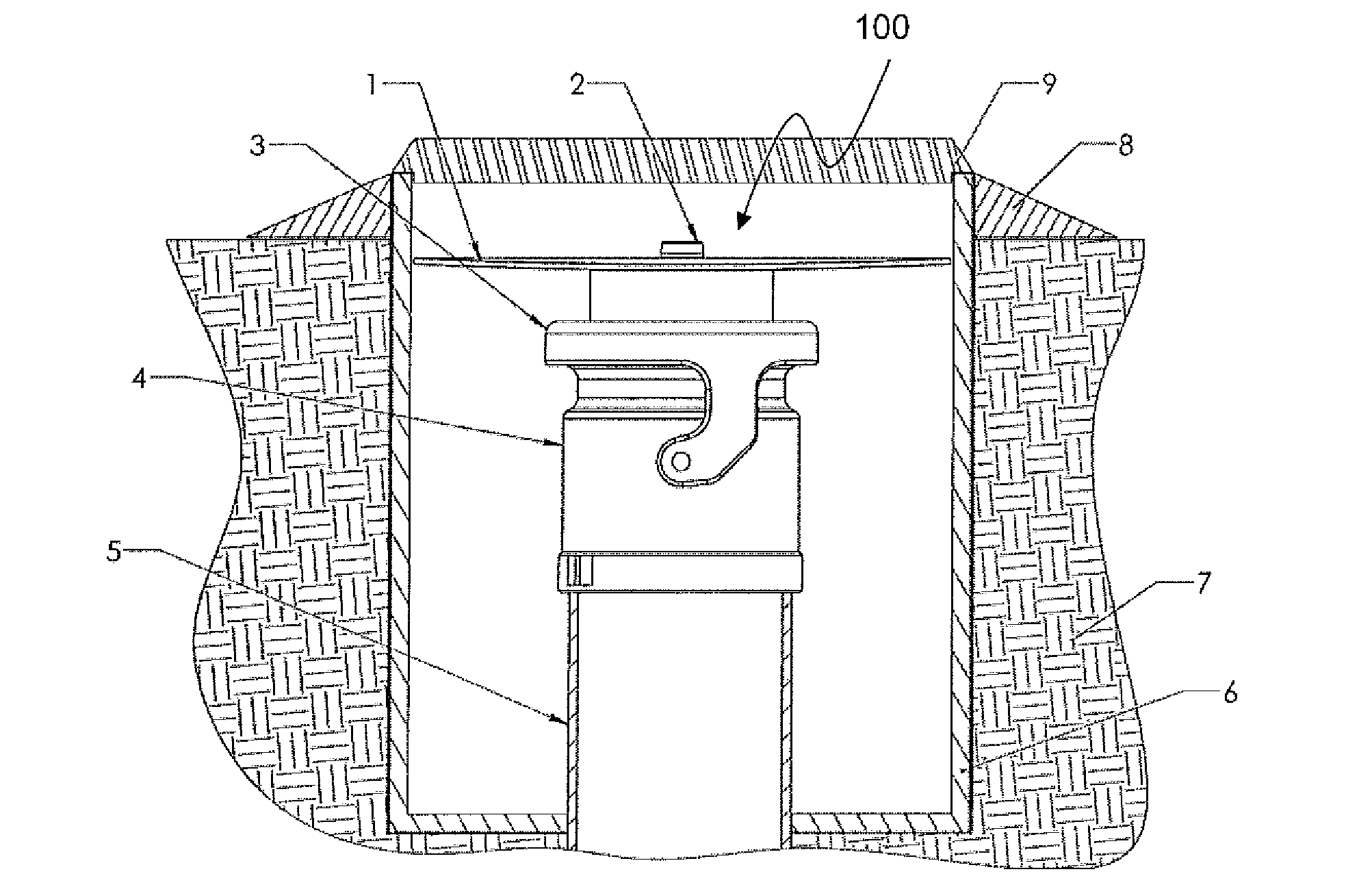
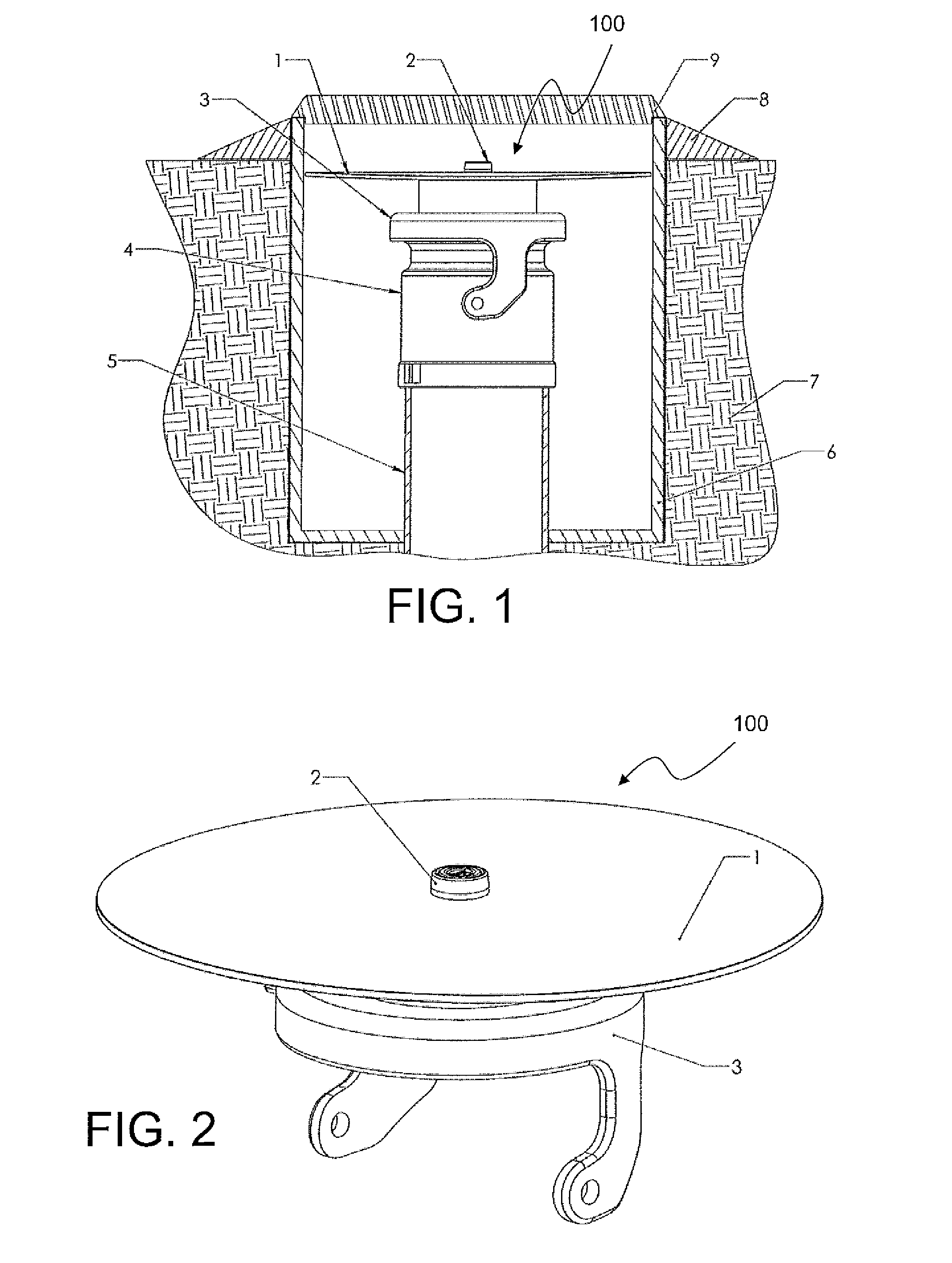
Underground tank lock
- Summary
- Abstract
- Description
- Claims
- Application Information
AI Technical Summary
Benefits of technology
Problems solved by technology
Method used
Image

Examples
first embodiment
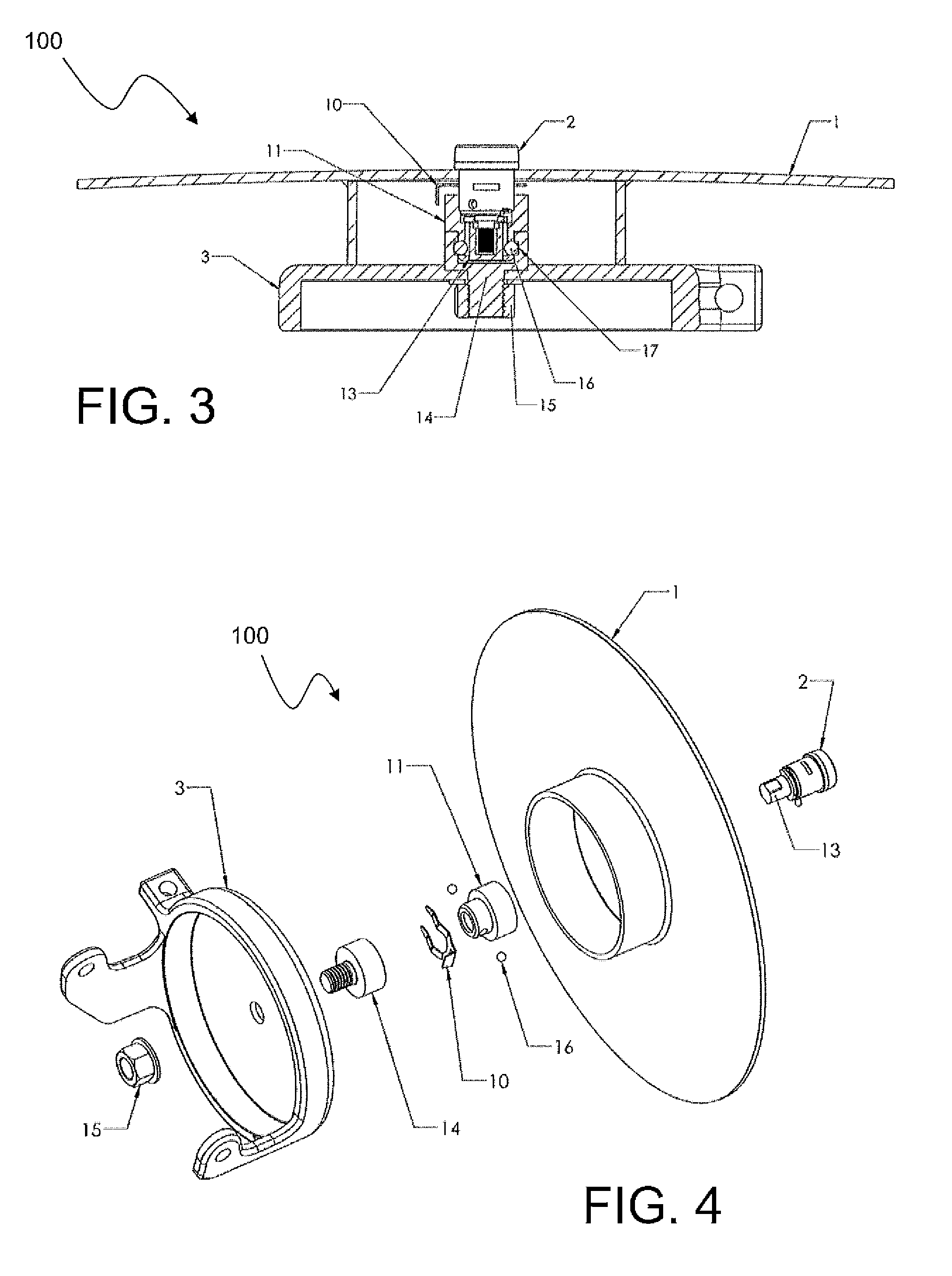
[0050]With reference now to FIGS. 5a and 5b, a second exemplary embodiment of the present subject matter will be described. FIG. 5a illustrates an isometric view of a present exemplary stand pipe and filler cap assembly including a lock housing 11′ secured to the filler cap 3 in accordance with a second exemplary embodiment of the present subject matter. FIG. 5b illustrates a cross section of the lock housing 11′ illustrated in FIG. 5a taken along section line 5b-5b thereof. As may be seen from an inspection of lock housing 11′, such lock housing differs from that of the first embodiment in that a cylindrical housing is provided in which a plurality of screw access holes 50 have been provided around the perimeter thereof. In the illustrated exemplary configuration, five such access holes have been provided, although such number is not a specific limitation of the present subject matter, so that alternatively, per present subject matter, an either greater number or fewer number of ac...
second embodiment
[0056]With further reference to FIG. 8, there is illustrated a blocking plate assembly generally 100′ wherein a skirt portion 1′ is added to the blocking plate 1, when compared with what is otherwise illustrated in present FIGS. 1 through 4. Skirt portion 1′ is either attached to or integrally formed with the perimeter of blocking plate 1 and extends within well housing 6 a distance sufficient, in cooperation with blocking plate 1, to cover at least a portion of filler cap 3 and, optionally, to cover at least a portion of coupling 4. In alternate present exemplary embodiments of the present subject matter, skirt 1′ may be extended to also cover a portion of standpipe 5.
[0057]It should be appreciated that, although the embodiment of FIG. 8 illustrates the use of the second embodiment of the lock configuration, that is, the lock configuration employing bolt 16′, such is not a limitation associated with the use of skirt 1′ together with blocking plate 1. Rather, the present blocking pl...
third embodiment
[0058]the present subject matter is described herein with reference to present FIGS. 9-11. FIG. 9, generally similar to present FIG. 1, illustrates a typical underground storage tank installation in combination with an exemplary locking sleeve assembly generally 900 in accordance with present technology. In a manner similar to that illustrated in FIG. 1, standpipe 905 is enclosed in well housing 906 and back filled, such as with concrete, earth, and / or other filler material 907. Well housing 906 is also provided with a flange 908 and capped with a cover 909.
[0059]As illustrated in FIG. 9, as well as in views in FIGS. 10 and 11, present exemplary locking sleeve assembly generally 900 corresponds to a locking sleeve 901 that is provided with a padlock type lock 910. Locking sleeve 901 generally corresponds to blocking plate 1 and alternative skirt 1′ illustrated in present FIG. 8 although in certain embodiments, the skirt portion of locking sleeve 901 may not require as large a diamet...
PUM
 Abstract
Description
Claims
Application Information
 - R&D
- Intellectual Property
- Life Sciences
- Materials
- Tech Scout
- Unparalleled Data Quality
- Higher Quality Content
- 60% Fewer Hallucinations
Browse by: Latest US Patents, China's latest patents, Technical Efficacy Thesaurus, Application Domain, Technology Topic, Popular Technical Reports.
© 2025 PatSnap. All rights reserved.Legal|Privacy policy|Modern Slavery Act Transparency Statement|Sitemap|About US| Contact US: help@patsnap.com