Engineering tool

Inactive Publication Date: 2009-12-31
HITACHI LTD
View PDF2 Cites 4 Cited by
  • Summary
  • Abstract
  • Description
  • Claims
  • Application Information

AI Technical Summary

Benefits of technology

[0010]In view of the aforementioned background circumstances, it is a first object of the present invention to provide an engineering tool which can increase a handleability by improving the operability of new-page beginning operation of logic sheets, and it is a second object of the present invention to provide an engineering tool which can increase a handleability by improving the operability of reference of logic sheets.
[0011]As mentioned above, in each of the logic sheets in the control logic, a connection relationship between the logic sheets is defined by a connection described on the logic sheet, and the connection has a function of having sheet connection information for defining the connection relationship of the logic sheet. In accordance with the present invention, the first object is attained by paying attention to such a connection function as to define the logic-sheets connection relationship and making the most of the connection function. That is, an operable button function is provided to a connection on a display screen. When the connection is operated as the button function, the logic sheet having defined sheet connection information possessed by the operated connection is used as a new-page candidate, and logic sheet information about the logic sheet of the new-page candidate is displayed on the display screen in the form of a list. As a result, the operability of new page beginning operation of the logic sheet is increased with an improved handleability.
[0013]In the aforementioned engineering tool, the new-page operability can be increased by utilizing the logic sheet information displayed in the form of a list in the operation of displaying a new-page target logic sheet. In this way, the aforementioned engineering tool of the present invention is designed to begin a new page of the logic sheet corresponding to the designated logic sheet information by a user who conducts designating operation for the logic sheet information displayed in the form of a list on the display screen.
[0015]In accordance with the present invention, as in the case of attaining the above first object, the above second object is attained by utilizing the function of the connection. That is, as in the above case, a button operable on a display screen is provided to a connection, so that, when the connection is operated as a button function, the logic sheet having sheet connection information possessed by the operated connection is used as a reference candidate, and the logic sheet of the reference candidate is displayed in a reduced manner so as to be located parallel to the logic sheet currently displayed on the display screen for the purpose of creation of the control logic or the like. As a result, the operability of reference of the logic sheet is increased and a handleability is improved.
[0017]In accordance with the above engineering tool of the present invention, the operability of new-page beginning operation of the logic sheets can be increased with an improved handleability, and the operability of reference of the logic sheets can be increased with an improved handleability.

Problems solved by technology

As a result, with respect to the new-page beginning operation, the user has to enter the sheet designation information, with a large user's burden and a bad handleability.
With regard to even reference of the logic sheets, the prior art engineering tool has a poor handleability.
In such a case, the prior art engineering tool requires the user to refer to the logic sheets while troublesomely repeating the new-page beginning operation based on the new-page button system.
If the displayed logic sheet is a user's reference target, then the user has to repeat the new-page beginning operation until a desired reference target logic sheet appears, which results in a large user's burden.

Method used


Image

  • Engineering tool
  • Engineering tool
  • Engineering tool

Examples


Embodiment Construction

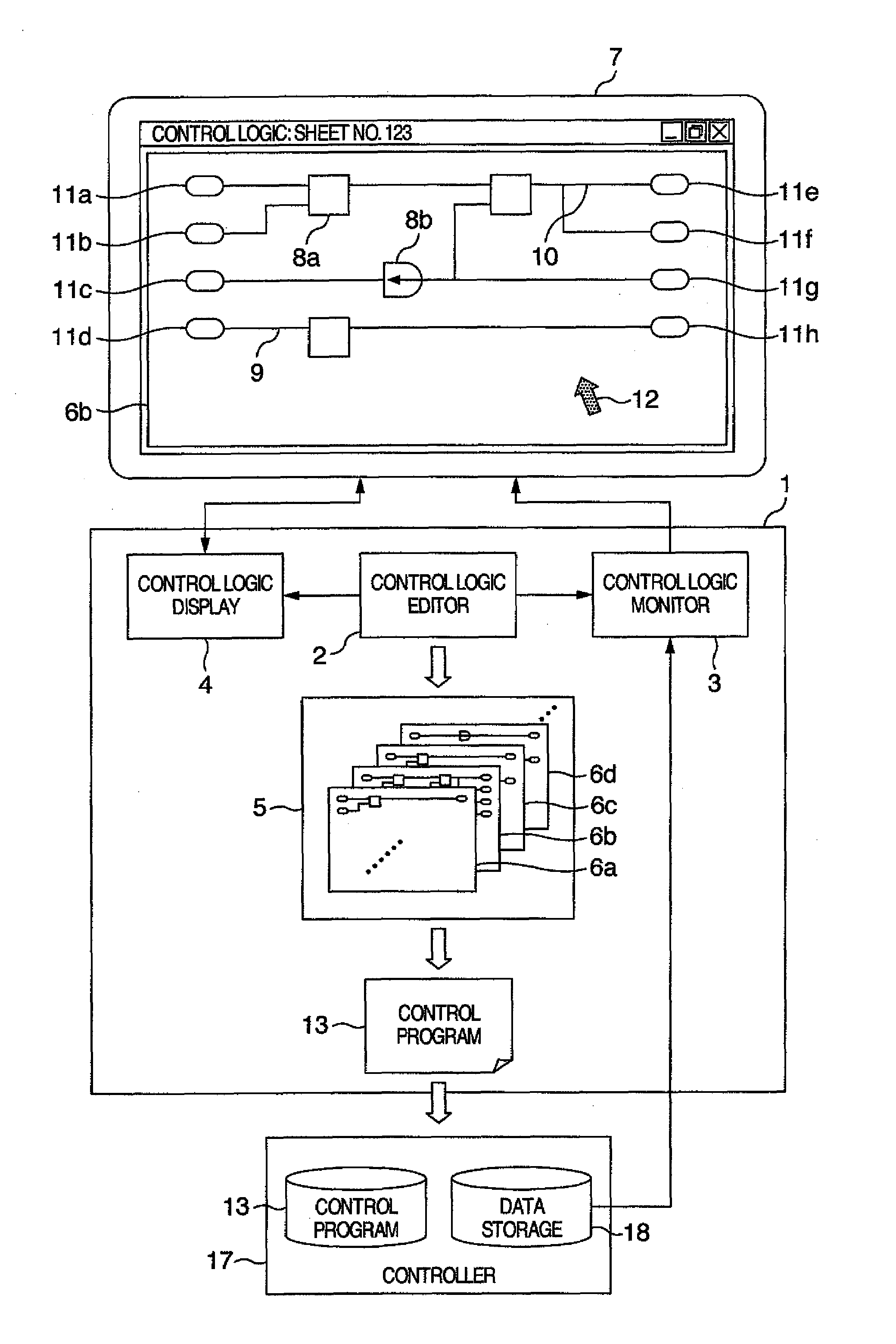
[0023]Explanation will be made as to an embodiment of the present invention. FIG. 1 shows a block diagram of a major arrangement of an engineering tool 1 in accordance with an embodiment of the present invention. The engineering tool 1 takes a form of a computer program or of a data processing device having the control program mounted therein. The engineering tool 1 includes a control logic editor 2, a control logic monitor 3, and a control logic display 4.

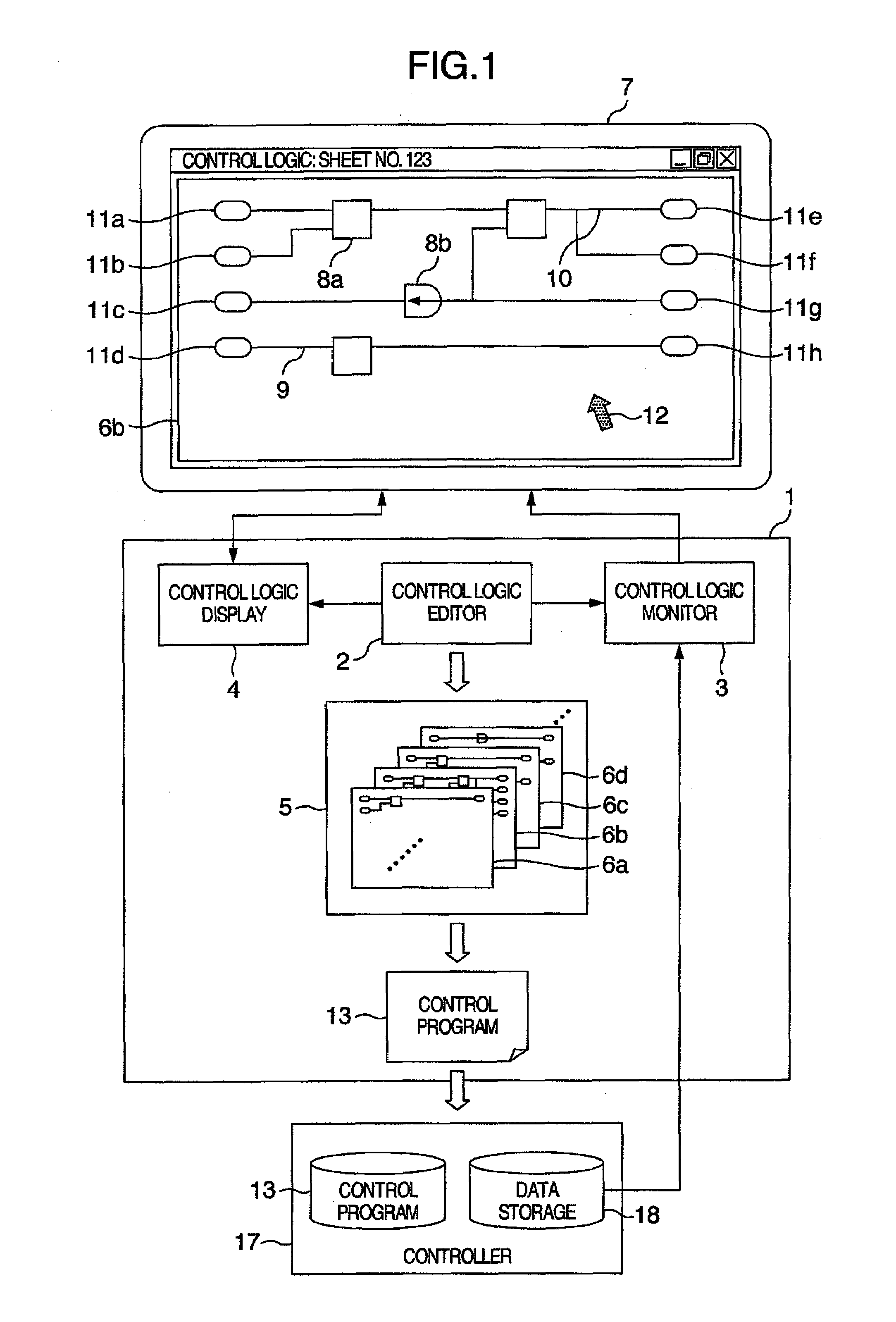
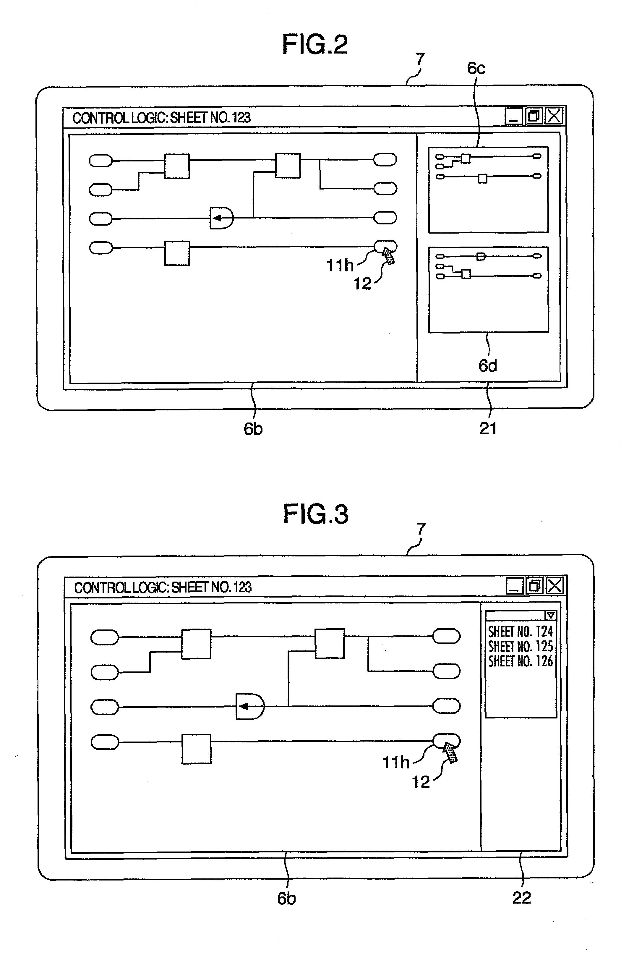
[0024]The control logic editor 2 functions to edit a control logic 5. The control logic 5 is made up of a plurality of logic sheets 6 (6a, 6b, . . . ), and description contents in the control logic 5 are partially described in each of the logic sheets 6. Editing of the control logic 5 is carried out by displaying one of the logic sheets 6 as an editing target in units of the logic sheet 6 on a display screen of a display device 7 and by using various sorts of function macros 8 (8a, 8b, . . . ) such as AND or OR previously prepared...


PUM


Abstract

In an engineering tool, the control logic is divided into the plurality of logic sheets to be edited, a connection having sheet connection information for defining a connection relationship between the logic sheets is described on the logic sheet, and the control logic is displayed on the display screen of a display device so as to begin a new page of the logic sheets of the control logic in units of the logic sheet in the control logic. In the engineering tool, a button function operable on the display screen is provided to a button function. When the connection is operated with a pointer, one of the logic sheets defined by the sheet connection information possessed by the operated connection is used as a new-page candidate, and a reduced list of the logic sheets of the new-page candidates is displayed on the display screen.

Description

BACKGROUND OF THE INVENTION[0001]The present invention relates to engineering tool and more particularly, to an engineering tool which is suitably used, for example, for plant control or the like in an thermal power plant.[0002]An engineering tool functions to support creation of a control program used in a controller of a plant or the like, or functions to support online monitoring of a control state under control of the control program (for example, see JP-A-2003-67007).[0003]The program creation support by the engineering tool is achieved by creating a control program through the conversion of a control logic edited by a user with use of various types of function macros (which are also called function boxes) and input and output lines indicative of input and output in such function macros. With respect to the editing of the control logic in this case, description contents in the control logic can be usually divided and described into a plurality of logic sheets. In other words, a...

Claims


Application Information

Patent Timeline
IPC IPC(8): G06F3/048G06F3/0484
CPCG05B2219/13144G05B19/056
Inventor MATSUDA, OSAMUAKATSU, TORU
Owner HITACHI LTD
Why Eureka
Try Eureka