
System and Method for Power Production Using a Hybrid Helical Detonation Device

a technology of hybrid helical detonation and pulsed detonation, which is applied in the direction of engine starters, electric generator control, lighting and heating apparatus, etc., can solve the problems of less efficient gasoline engines than diesel engines, the fluid density of the fluid drops significantly, and the overall length of the engine suffers a very small drop, so as to reduce the overall length of the engine, and keep the engine to a small and practical form

Inactive Publication Date: 2009-12-31
BOARD OF RGT THE UNIV OF TEXAS SYST
View PDF20 Cites 8 Cited by
  • Summary
  • Abstract
  • Description
  • Claims
  • Application Information

AI Technical Summary

Benefits of technology

"The present invention provides an apparatus, system, and method to generate useable electric power using the output from a PDE. The invention compensates for the pulsing nature of the PDE, high temperatures, pressure loading, and matches the rotational speeds and torques of the turbine and generator. The invention also includes a modified helical tube detonation chamber, a means for rapid filling of a long detonation tube, and a source of scalable power. The technical effects of the invention include improved efficiency and reliability of the detonation process, reduced size and weight of the engine, and increased power output."

Problems solved by technology

Gas turbines have a drawback in that while the total temperature is increased, the total pressure of the fluid suffers a very small drop and the density of the fluid drops significantly.
It is widely known that the more popular gasoline engines are less efficient than diesel engines.
While PDEs do have advantages over conventional jet engines, they also pose challenges to their use in electric power generation.
For example, when integrating a turbine with a PDE, the turbine blades will be subjected to shock waves, very high pressures and temperatures.

Method used


Image

  • System and Method for Power Production Using a Hybrid Helical Detonation Device
  • System and Method for Power Production Using a Hybrid Helical Detonation Device
  • System and Method for Power Production Using a Hybrid Helical Detonation Device

Examples


Embodiment Construction

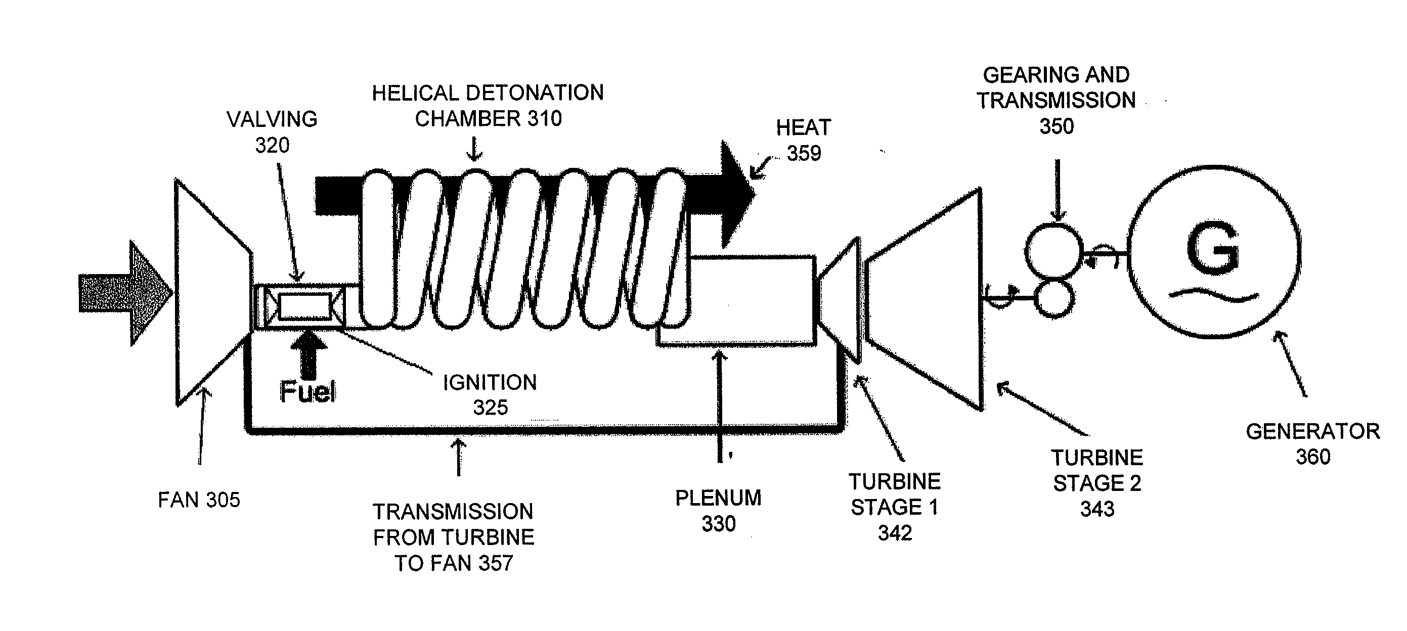
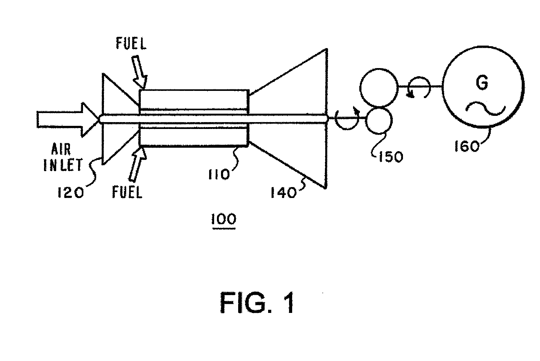
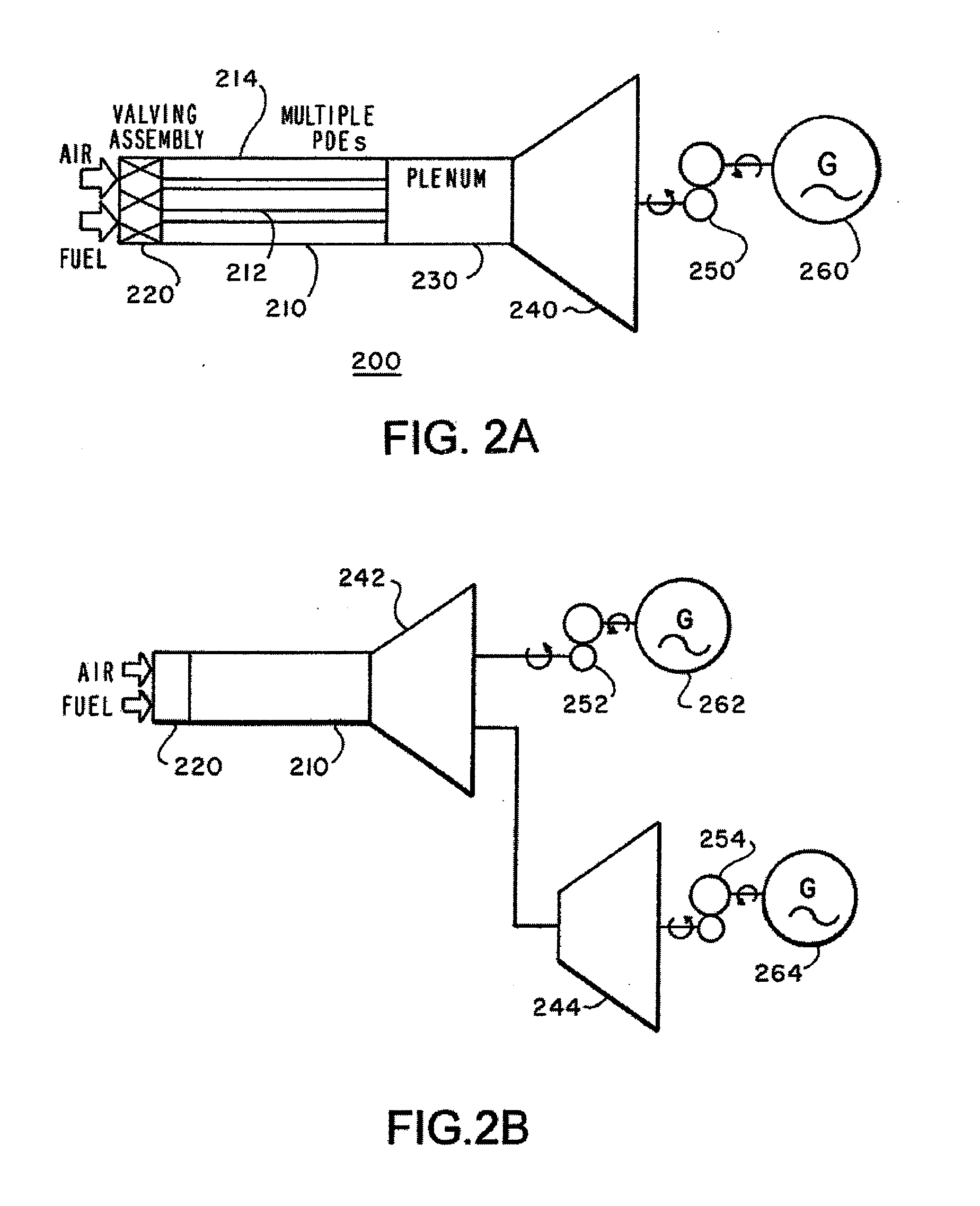
[0026]The invention, as defined by the claims, may be better understood by reference to the following detailed description. The description is meant to be read with reference to the Figures contained herein. This detailed description relates to examples of the claimed subject matter for illustrative purposes, and is in no way meant to limit the scope of the invention. Element numerals are consistent, where possible, across Figures. The specific aspects and embodiments discussed herein are merely illustrative of ways to make and use the invention, and do not limit the scope of the invention.

[0027]A pulsed detonation engine (PDE) in its simplest form essentially consists of a constant area tubular combustion (detonation) chamber with inlet valves to control the flow of fluid into the detonation chamber. The PDE cycle has four states. In the filling stage, the fuel and air inlet valves are opened to allow a fuel and air mixture to fill the tube. This is followed by the initiation and d...


PUM


Abstract

The system and method described herein uses a hybrid pulsed detonation engine (PDE) system to drive a turbine that powers an electric generator. The combustion chamber of the PDE is shaped in a helical form, so that the external length of the section is reduced, while maintaining the distance for acceleration to detonation. This allows the achievement of deflagration to detonation transition without the help of turbulence enhancing obstacles, while keeping the overall size of the detonation tube small. The PDE output can be scaled by: increasing the cross sectional area of the detonation chamber; increasing the number of detonation tubes; and increasing the frequency of operation of the PDE. The replacement of conventional deflagrative internal combustion engines, including gas turbines and reciprocating engines, with pulsed detonation engines for electric power generation, may provide fuel savings and have a lower environmental impact.

Description

CROSS-REFERENCE TO RELATED APPLICATIONS[0001]This is a continuation of application Ser. No. 11 / 877,358 filed Oct. 23, 2007, abandoned on ______.BACKGROUND OF THE INVENTION[0002]The present invention relates generally to electric power generation. More particularly, the present invention provides a system and method for using hybrid pulsed detonation engines (PDEs) in electric power generation.[0003]It is well accepted that detonation is a much more efficient form of combustion than deflagration. Consequently, PDEs have a very high theoretical efficiency. Due, in part, to their high efficiencies, PDEs are receiving increased interest as a viable propulsion system for supersonic and hypersonic aircraft. The Chapman-Jouget (C-J) detonation process yields higher pressures and temperatures in cycle thermal efficiencies, which exceeds that of conventional jet engines.[0004]In conventional gas turbine engines, a compressor is used to increase the static pressure of the fluid before heat ad...

Claims


Application Information

Patent Timeline
Patent Type & Authority Applications(United States)
IPC IPC(8): H02P9/04F02C5/02F02C7/00
CPCF02C5/12F05D2250/25Y02E20/14F23R7/00
Inventor LU, FRANK K.PANICKER, PHILIP K.WILSON, DONALD R.LI, JIUN-MING
Owner BOARD OF RGT THE UNIV OF TEXAS SYST
Learn More