
Fire poker

Active Publication Date: 2009-12-24
BIDDINGTON DALE
View PDF14 Cites 2 Cited by
  • Summary
  • Abstract
  • Description
  • Claims
  • Application Information

AI Technical Summary

Benefits of technology

[0008]According to an aspect of the present invention, there is provided a fire poker comprising a generally elongated body portion, a handle adapted to co-operate with the body portion and facilitate the manipulation and control thereof; the handle being disposed in the general vicinity of one end of the body portion; a structure which is adapted, shaped and dimensioned so as to facilitate the control and maintenance of the fire and selected arrangement of components thereof, the structure being adapted for co-operation with the body portion in a position remotely disposed from the handle; wherein the normally elongated extension of the body portion deviates tangentially at a selected juncture along its length to a degree sufficient to facilitate and enhance the efficient operation and control thereof.

Problems solved by technology

Although this poker has a straight segment that extends past the hook portion by about one inch, this distance is not significant enough to allow for the straight segment to be utilized for stoking a fire without having the hook portion interfere with the process.
Furthermore, the nature of the shaft of the fire poker will typically result in the fire being stoked in essentially a downward direction.
This makes the manipulation of the fuel of the fire substantially more difficult, and extra energy is required to be expended by the user in order to stoke the fire in a satisfactory manner.
In this design, the hook member is located so close to the tip of the shaft that manipulation of the fuel of the fire with the tip of the shaft independent of the hook, or the hook independent of the tip, becomes essentially impossible.
This angle provides for less efficiency when manipulating the fire, and delicate displacement of, e.g. logs of the fire, becomes difficult.
This provides for instances where the handle may fall off or break off from the shaft, making the poker considerably more difficult to wield.

Method used


Image

  • Fire poker
  • Fire poker
  • Fire poker

Examples


Embodiment Construction

[0034]As used in the specification as well as in the appended claims, the term “about” is utilized to modify various numerical values. In this context, the term “about” should be construed to mean any value that is within 10% of the stated value. For example, if the term “about” is used to modify a value of 20°, then the value should then be interpreted as representing the range of 18° to 22°, that is, the value ±10%.

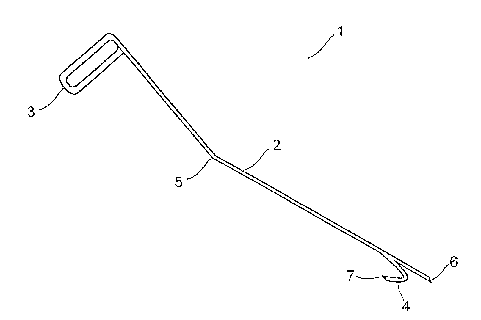
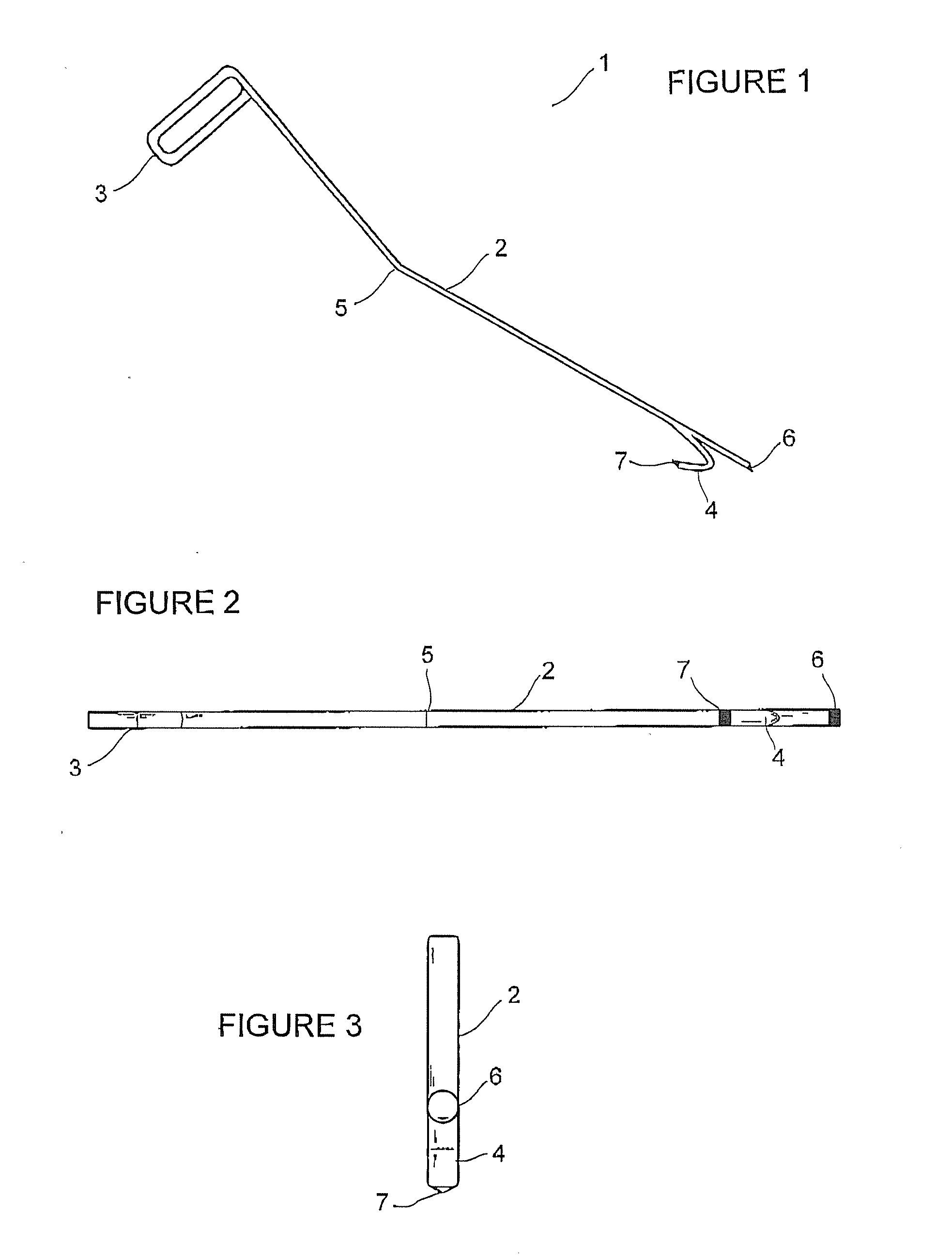
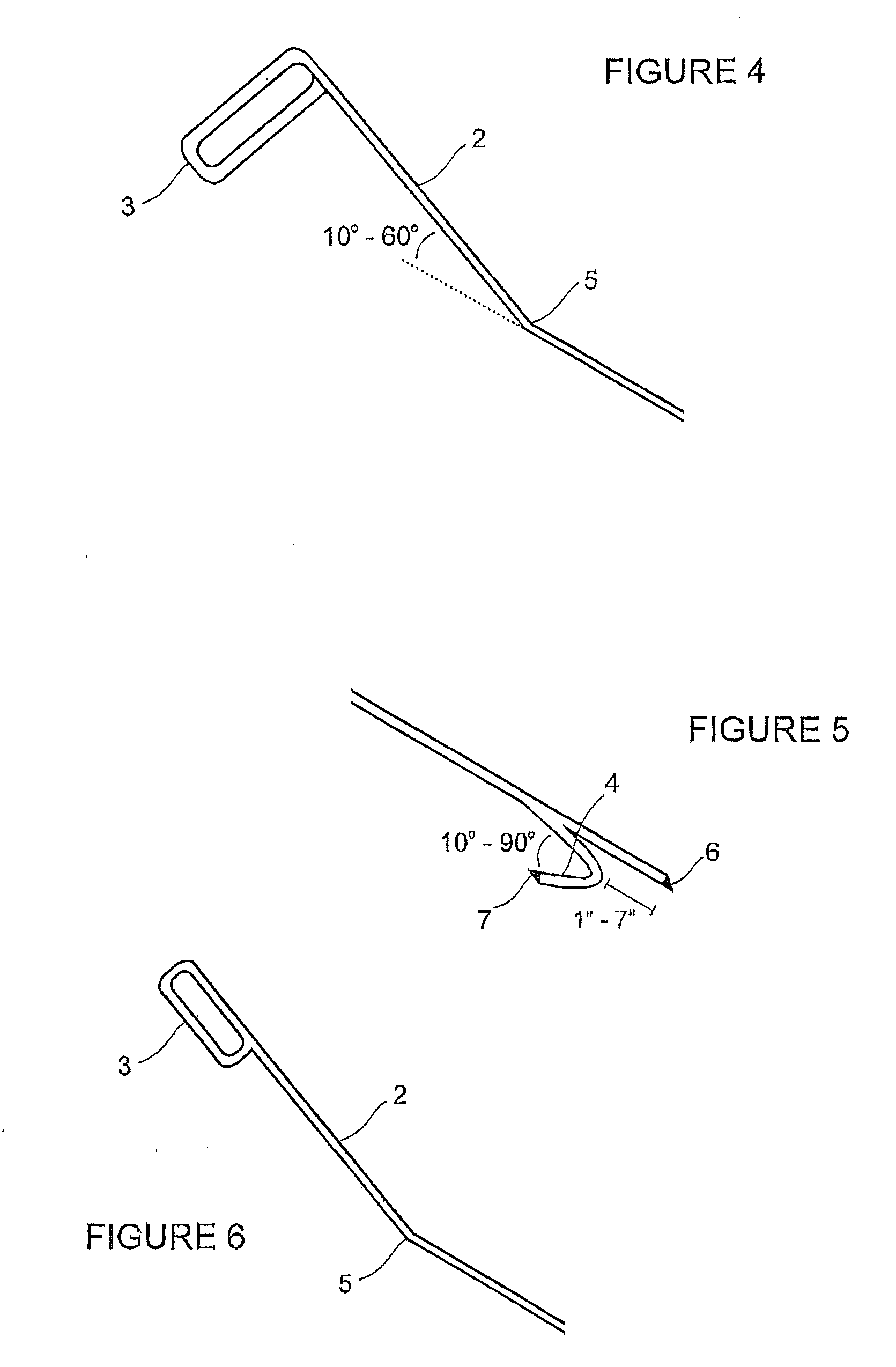
[0035]FIGS. 1, 2 and 3 illustrate a preferred embodiment of the fire poker 1 of the present invention. The fire poker 1 comprises a shaft 2, a hook member 4 extending longitudinally from one end of the shaft 2, and a handle 3 at the opposing end of the shaft 2.

[0036]The poker 1 as illustrated in FIG. 1 has a bend 5 in the shaft 2. The bend 5 can occur anywhere along the length of the shaft 2, i.e. anywhere in the shaft 2 spanning the length between the handle 3 to the hook member 4. Preferably the shaft 2 is bent at an angle in the range of about 10° to about 60°. More ...


PUM


Abstract

A fire poker is provided which is comprised of an elongate shaft, a handle at one end of the shaft and a longitudinal hook member near the second end of the shaft. The shaft has a bend located at a position between the handle and the hook member. Alternatively, the shaft may have a plurality of bends located at positions between the handle and the hook member. The plurality of bends divides the shaft into a plurality of sections, and the section of the shaft that contacts the hook member is preferably in the same plane as the section that contacts the handle. The at least one bend in the shaft of the fire poker provides for a device that is more comfortable to wield, is better from an ergonomic perspective and allows for considerably easier manipulation of the fuel of a fire.

Description

RELATED APPLICATION[0001]This application claims priority to Canadian Application No. 2,635,194 filed Jun. 18, 2008, the entirety of which is incorporated herein by reference.FIELD OF THE INVENTION[0002]The invention relates to fire pokers. In particular, the invention relates to fire pokers that are designed to allow for easier manipulation of the fuel of a fire.BACKGROUND OF THE INVENTION[0003]A fire poker (also known as a “stoker”) is a short, rigid rod, preferably of fireproof material, used to adjust coals and / or wood fuel, burning in a fireplace or a firepit. It is often metallic and sometimes has a point at one end for pushing burning materials (or a hook for pulling / raking, or a combination thereof) and a handle at the opposite end.[0004]An example of a fire poker as found in the prior art can be seen in U.S. Pat. No. 7,131,675. This fire poker has a hook portion attached at one end of a shaft, with a handle at the opposing end. The handle incorporates such features as a dir...

Claims


Application Information

Patent Timeline
IPC IPC(8): F24B15/00
CPCF24B15/002
Inventor BIDDINGTON, DALE
Owner BIDDINGTON DALE
Learn More