
Configurable welding interface for automated welding applications

Active Publication Date: 2009-12-17
ILLINOIS TOOL WORKS INC
View PDF12 Cites 148 Cited by
  • Summary
  • Abstract
  • Description
  • Claims
  • Application Information

AI Technical Summary

Benefits of technology

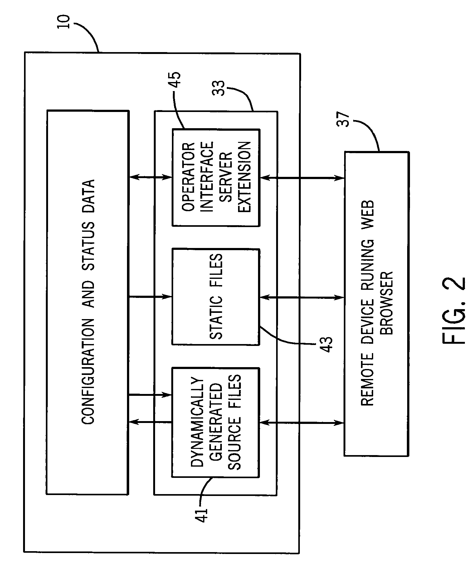
[0006]In one aspect of the invention, a welding power source is provided. The power source includes a power supply, a controller coupled to the power supply to provide weld parameter control signals to the power supply, and an embedded web server in communication with the controller and a remote client browser. The web server is programmed to allow a user accessing

Problems solved by technology

The need for improved monitoring, moreover, has increased in recent years as welding personnel on the factory floor are frequently inexperienced in welding operations.
Often, operators are minimally trained, and cannot properly choose weld parameters, or identify and correct for problems encountered during welding processes and weld set-up.

Method used


Image

  • Configurable welding interface for automated welding applications
  • Configurable welding interface for automated welding applications
  • Configurable welding interface for automated welding applications

Examples


Embodiment Construction

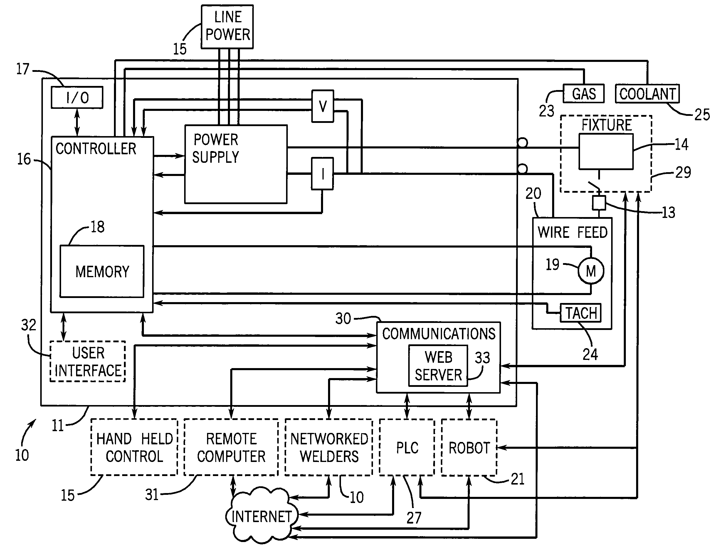
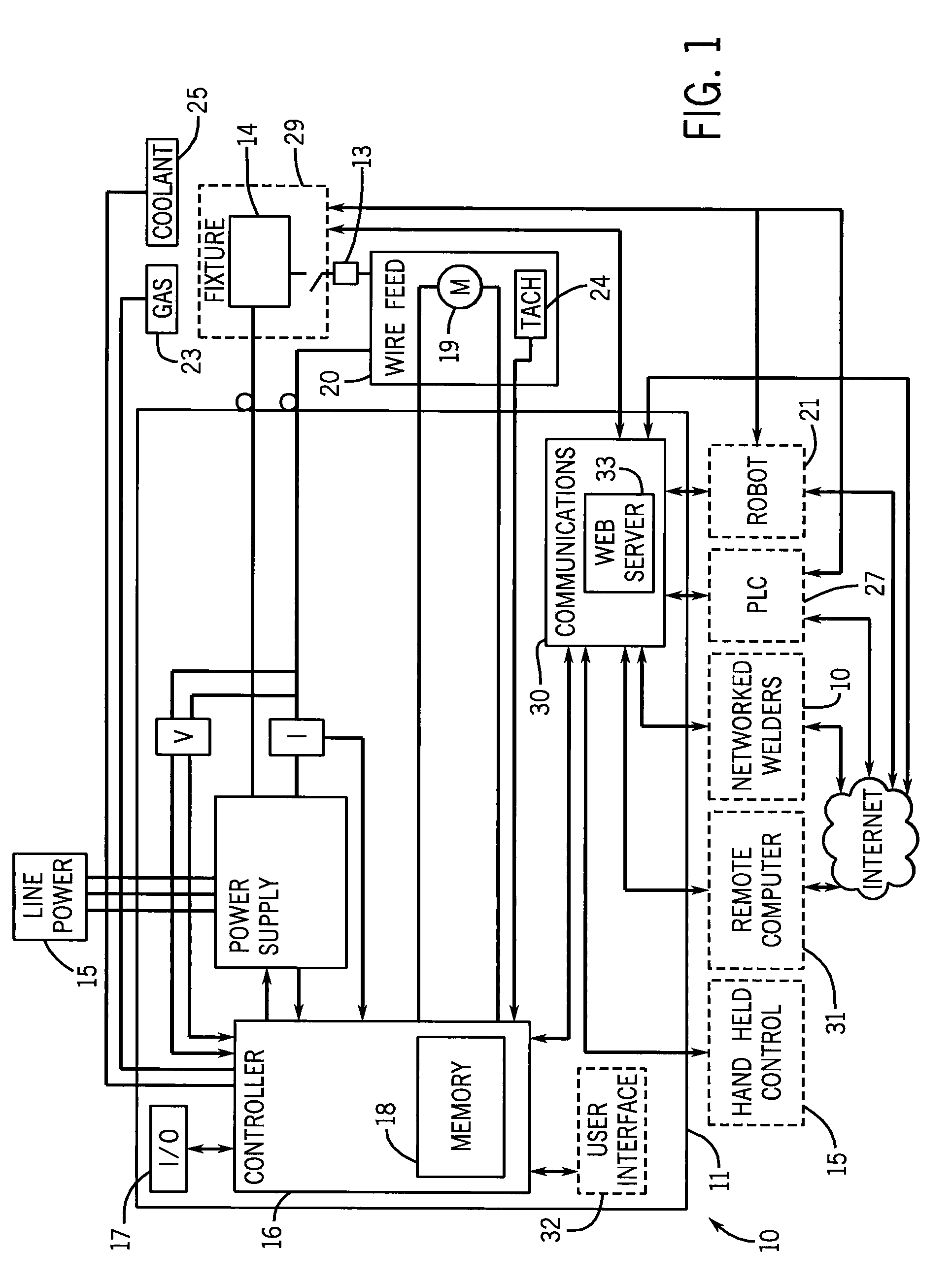
[0020]Referring now to the Figures and more particularly to FIG. 1, an exemplary welding system 10 for automatic and semi-automatic welding is shown. The welding system 10 includes a housing 11 containing a power supply 12, a controller 16, and a communications system 30 for communicating with external components. These external components can be, for example, the components of a welding cell, including flexible or hard automation components, such as a welding robot 21, a programmable logic controller (PLC) 27, and fixtures 29. Alternatively, or additionally, the external components can include one or more computer or computer network 31, provided in a factory automation system. The communications system 30 can be connected to a series of networked welding systems 10, either directly or through one or more computer 31. Bi-directional communications between the welding system 10 and external devices are preferably provided through an embedded web server 33 in communications system 30...


PUM

PropertyMeasurementUnit
Electrical inductanceaaaaaaaaaa

Abstract

A welding power source including an embedded web server provides access to an operator at a remote web browser. From the remote web browser, the user is provided access to weld functions, and can selectively choose between weld functions that can be displayed and controlled from the remote web browser. The weld functions that can be accessed include control functions, which allow an operator to activate welding functions such as a jog or purge function; a command function, which allows an operator to provide a command level for a voltage, wire feed speed, or other parameter; and a display function, which provides access for an operator to display welding command and actual feedback values. The operator can also selectively view diagnostic data, including weld state data, error data, and operational voltage and current levels within the power source, such as motor voltage and input voltage levels. After an operator selects parameters to be displayed or controlled from the browser, the selected functions can be stored and recalled as a web page.

Description

FIELD OF THE INVENTION[0001]The present invention is directed to a method and apparatus for configuring welding operations.BACKGROUND OF THE INVENTION[0002]As the level of automation has increased in mass production facilities, and the speed of welding operations has increased, it has become increasingly important for management personnel to monitor and control welding parameters, processes, and weld cell set-up parameters in a facility. Proper monitoring and control helps to ensure consistent and proper joining of materials, to ensure that completed welds fall within predetermined quality parameters, and to ensure that material waste and operational downtime is avoided.[0003]The need for improved monitoring, moreover, has increased in recent years as welding personnel on the factory floor are frequently inexperienced in welding operations. Often, operators are minimally trained, and cannot properly choose weld parameters, or identify and correct for problems encountered during weld...

Claims


Application Information

Patent Timeline
IPC IPC(8): G06F3/048
CPCB23K9/0953G05B19/406G05B2219/34038G05B2219/35289H04L67/42G05B2219/45135G05B15/02G06F3/04842G05B2219/36283H04L67/025H04L67/01
Inventor CASNER, BRUCE ALANCASNER, DANIEL THOMAS DUCKERT
Owner ILLINOIS TOOL WORKS INC
Learn More