Method of selectively adapting material properties across a rock bit cone

a technology of material properties and rock bits, applied in the field of earthwork tools, can solve the problems of more inserts falling, the body of the rotatable cone may wear, and the hardfacing application may be relatively labor-intensiv

Inactive Publication Date: 2009-12-17
BAKER HUGHES INC
View PDF105 Cites 4 Cited by
  • Summary
  • Abstract
  • Description
  • Claims
  • Application Information

AI Technical Summary

Benefits of technology

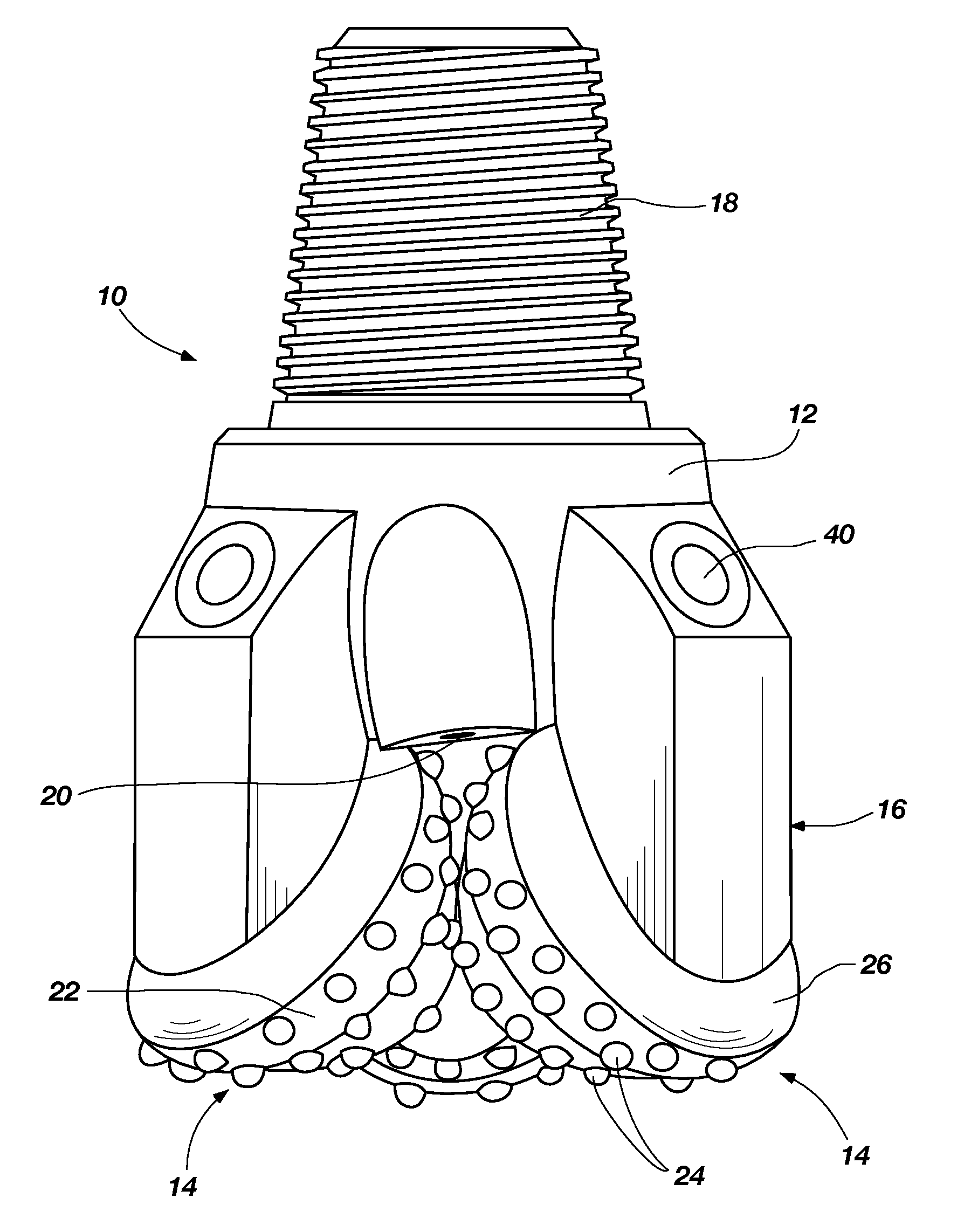
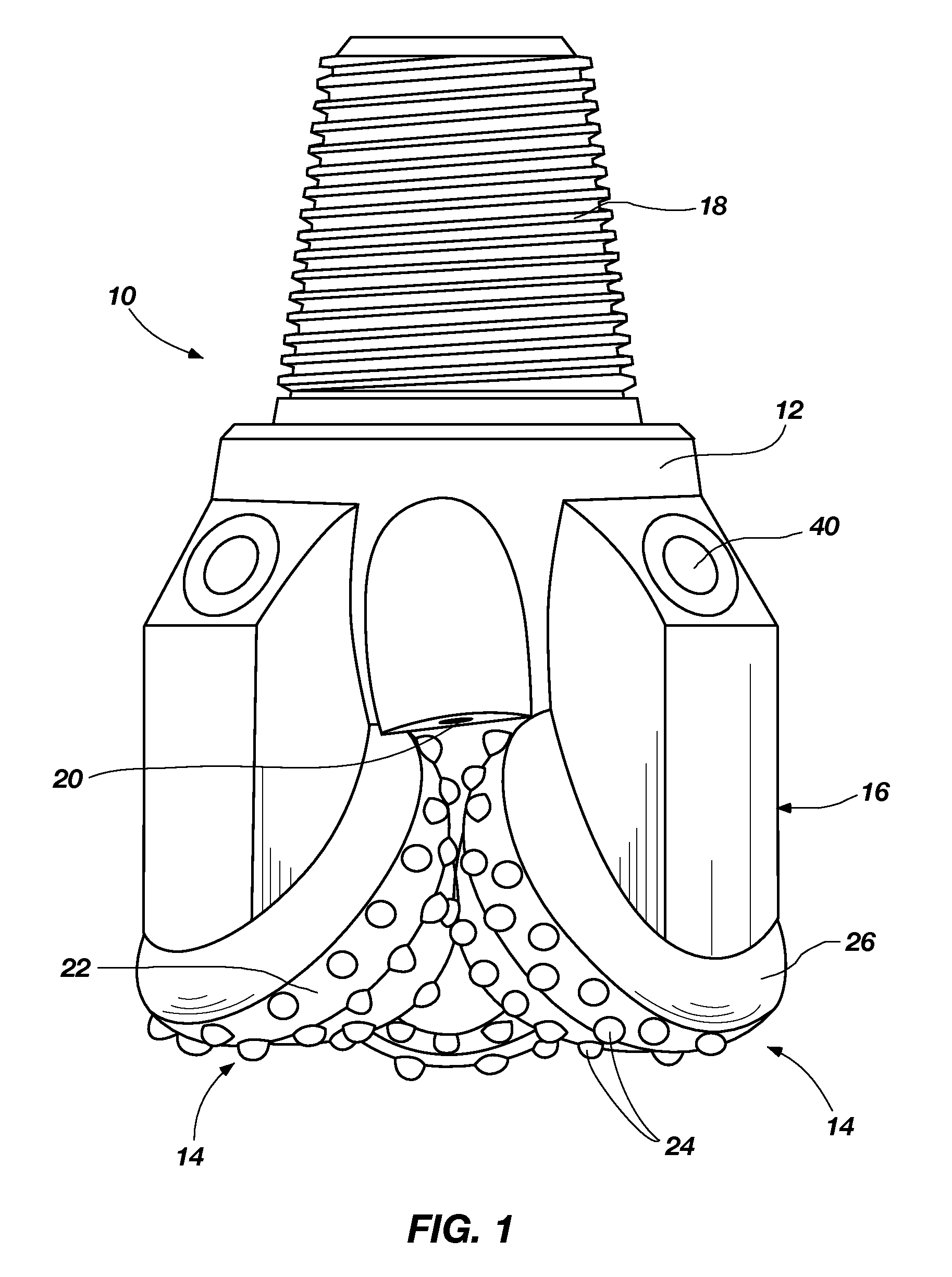
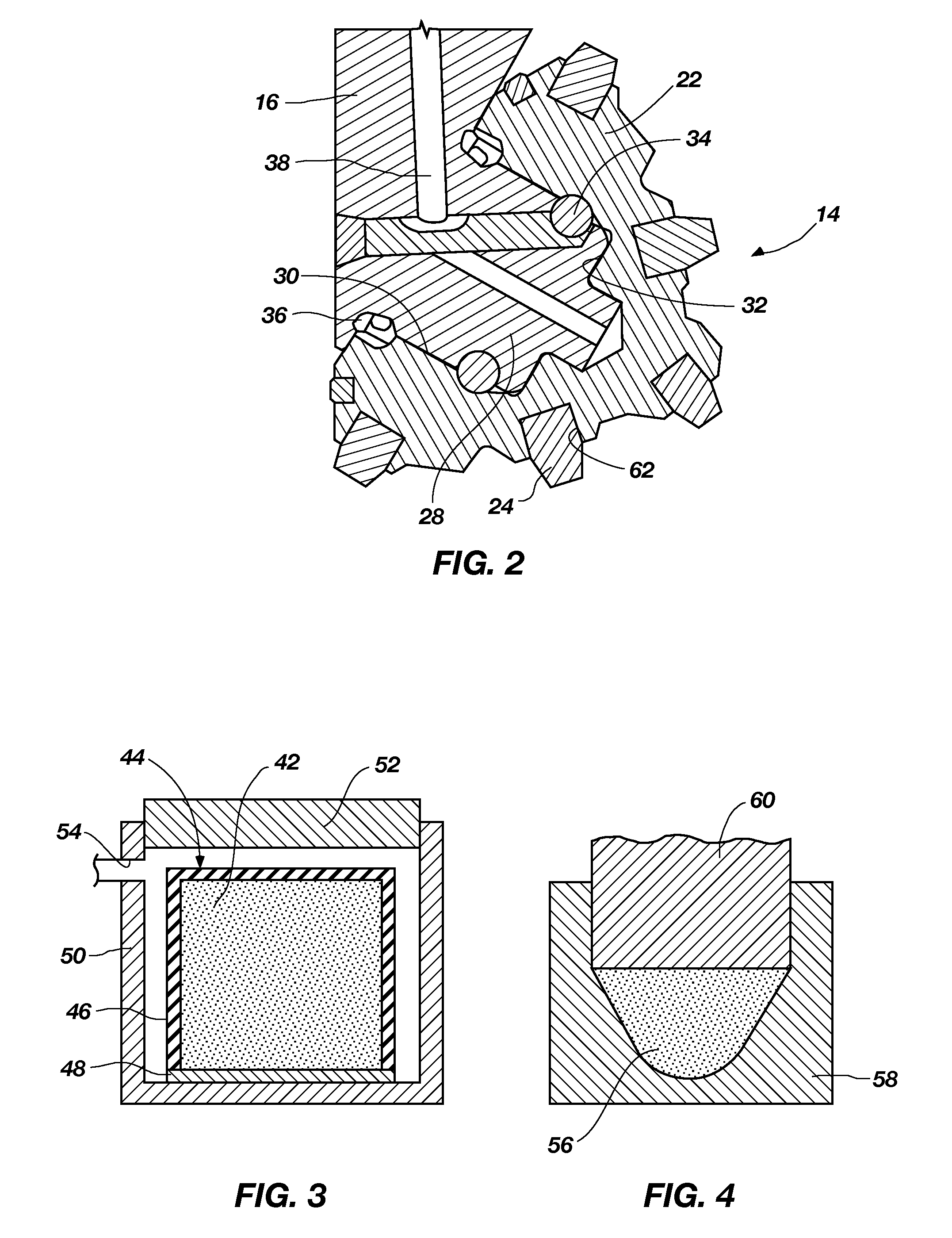
[0008]In some embodiments, the present invention includes methods of forming cutter assemblies for use on earth-boring tools. The methods include sintering a less than fully sintered cone structure to a desired final density to fuse at least one cutting element, also termed “inserts” herein, to the cone structure, and hard particles selectively located between rows of inserts in a matrix material.

Problems solved by technology

During drilling operations, it is possible that a body of a rotatable cone may wear to the extent that one or more inserts may fall out from the hole in which it was secured due to excessive wear of the region of the cone body surrounding the hole.
Hardfacing applications may be relatively labor intensive, and hardfacing thickness and uniformity of coverage may be difficult to control in a repeatable manner.
Furthermore, application of hardfacing material to the teeth of a rotatable cone may reduce the sharpness of the cutting edges of the teeth.
However, sharpening the hardfaced teeth by grinding adds another step and substantial labor and machining cost in a process for manufacturing a roller cone bit.

Method used


Image

  • Method of selectively adapting material properties across a rock bit cone
  • Method of selectively adapting material properties across a rock bit cone
  • Method of selectively adapting material properties across a rock bit cone

Examples


Embodiment Construction

[0025]The illustrations presented herein are not meant to be actual views of any particular material, apparatus, system, or method, but are merely idealized representations which are employed to describe the present invention. Additionally, elements common between figures may retain the same numerical designation.

[0026]The term “green” as used herein means unsintered.

[0027]The term “green structure” as used herein means an unsintered structure comprising a plurality of discrete particles held together by a binder material.

[0028]The term “brown” as used herein means partially sintered.

[0029]The term “brown structure” as used herein means a partially sintered structure comprising a plurality of particles, at least some of which have partially grown together to provide at least partial bonding between adjacent particles. Brown structures may be formed by partially sintering a green structure.

[0030]The term “sintering” as used herein means densification of a particulate component involv...


PUM

PropertyMeasurementUnit
diameteraaaaaaaaaa
diameteraaaaaaaaaa
pressureaaaaaaaaaa

Abstract

Methods of forming cutter assemblies for use on earth-boring tools include sintering a cone structure to fuse one or more cutting elements thereto and having a hardened land area. In some embodiments, one or more green, brown, or fully sintered cutting elements may be positioned on a green or brown cone structure prior to sintering the cone structure to a final density. Cutter assemblies may be formed by such methods, and such cutter assemblies may be used in earth-boring tools such as, for example, earth-boring rotary drill bits and hole openers.

Description

FIELD OF THE INVENTION[0001]The present invention generally relates to earth-boring tools having one or more rotatable cones. More particularly, embodiments of the present invention relate to methods of forming cutter assemblies having a cone comprising a particle-matrix composite material for use in such earth-boring tools having variable properties across the cone, to cutter assemblies formed by such methods, and to earth-boring tools that include such cutter assemblies.BACKGROUND OF THE INVENTION[0002]Earth-boring tools, including rotary drill bits, are commonly used for drilling boreholes or wells in earth formations. One type of rotary drill bit is the roller cone bit (often referred to as a “rock” bit), which typically includes a plurality of conical cutting elements (often referred to as “cones” or “cutters”) secured to legs dependent from the bit body. For example, the bit body of a roller cone bit may have three depending legs each having a bearing pin. A rotatable cone may...

Claims


Application Information

Patent Timeline
Patent Type & Authority Applications(United States)
IPC IPC(8): E21B10/08
CPCE21B10/50
Inventor LYONS, NICHOLAS J.
Owner BAKER HUGHES INC
Why Eureka
Try Eureka