
Inner blade for electric shaver

Inactive Publication Date: 2009-12-17
PANASONIC CORP
View PDF2 Cites 8 Cited by
  • Summary
  • Abstract
  • Description
  • Claims
  • Application Information

AI Technical Summary

Benefits of technology

[0008]The present invention is conceived to solve the above mentioned conventional problems, and it is purposed to provide an inner blade for electric shaver which can cut off the beard, moustache or whisker substantially perpendicular to the protruding direction thereof in a root portion of the beard, moustache or whisker.
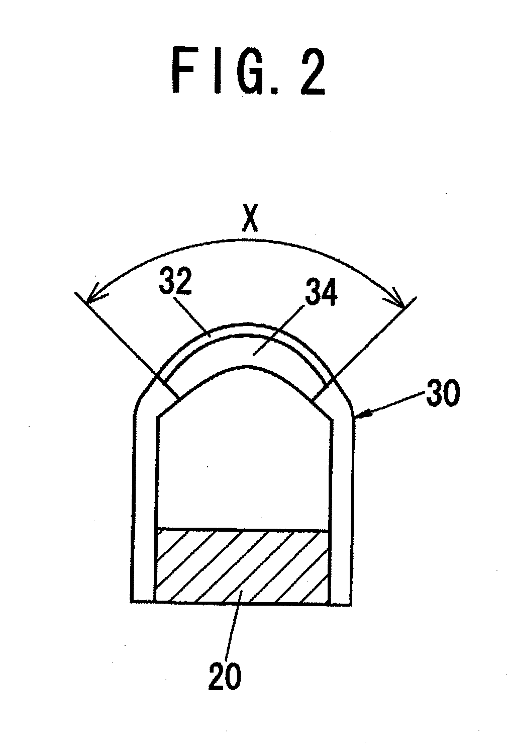
[0010]According to such a configuration, a beard, moustache or whisker, which is introduced into a center portion of the beard / moustache / whisker introduction aperture of the outer foil blade when cutting the beards, moustaches or whiskers, starts to move following to motion of the blade element of the inner blade, and it is started to be cut at a portion near to root thereof by the blade element of the inner blade before reaching to a front cutting edge of the outer foil blade. Since the radius of curvature R of the cusp of the cutting edge is selected to be smaller than the conventional one shown in the above WO2003 / 016000, cutting of the beard, moustache or whisker can be continued without push down of the beard, moustache or whisker. Consequently, cut face of the beard, moustache or whisker can be cut substantially perpendicular to protruding direction of the beard, moustache or whisker in the root portion of the beard, moustache or whisker, so that it is possible to cut the beards, moustaches or whiskers shorter without repeating cutting in several times like the conventional case.

Problems solved by technology

Therefore, as shown in FIG. 11C, a front end portion of the beard, moustache or whisker H which is cut in the condition of pushed down slants, and consequently, there is a problem that the beard, moustache or whisker H after cutting cannot be finished short.

Method used


Image

  • Inner blade for electric shaver
  • Inner blade for electric shaver
  • Inner blade for electric shaver

Examples


Embodiment Construction

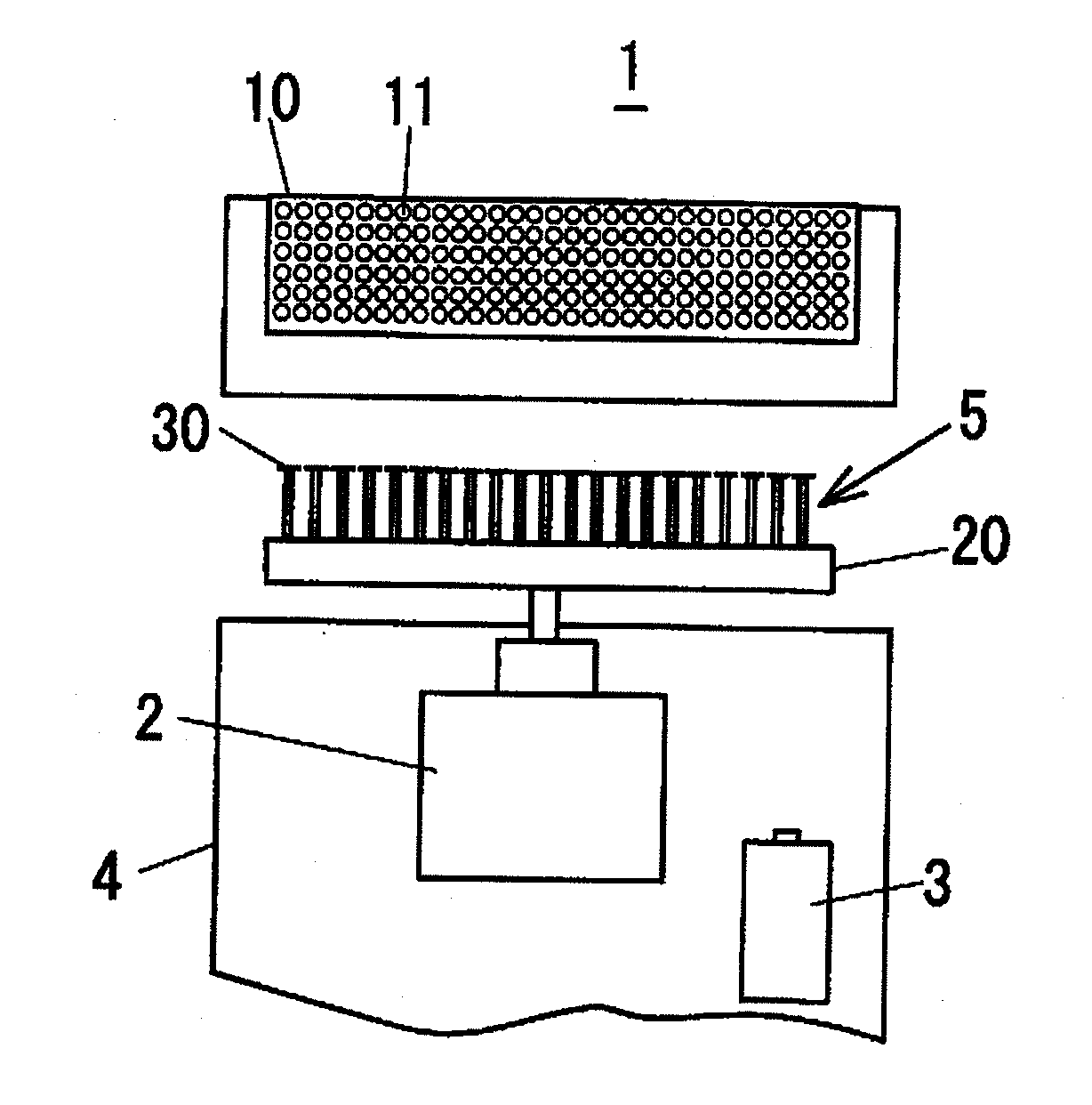
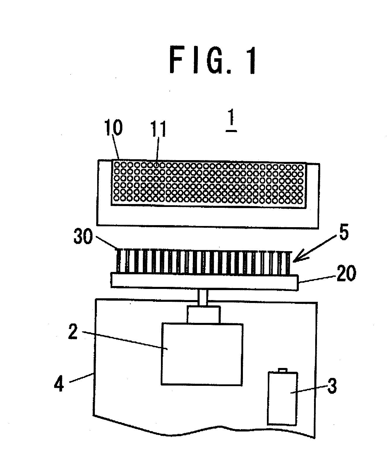
[0023]An inner blade for electric shaver in accordance with an embodiment of the present invention is described with reference to drawings. As shown in FIG. 1, an inner blade 5 for electric shaver in accordance with the present invention is applied to a reciprocation driving type electric shaver 1, and it comprises plural pieces of blade elements 30 which are arranged in parallel with each other on a base 20 made of a synthetic resin. The reciprocation driving type electric shaver 1 has a driving mechanism 2 which is configured with a motor contained in a housing 4 and so on, and a rechargeable battery 3, for example. The base 20 of the inner blade 5 is coupled with the driving mechanism 2, and thereby, the inner blade 5 is held in a condition to protrude outward from a top end of the housing 4. An outer foil blade 10 has a lot of beard / moustache / whisker introduction apertures 11 formed approximately uniformly, and the outer foil blade 10 is installed on the top end of the housing 4...


PUM


Abstract

In an inner blade (5) for electric shaver comprising plural blade elements (30) which are supported on a base (20), and reciprocally driven parallel to an outer foil blade (10) having beard / moustache / whisker introduction apertures (11) so as to cut beards, moustaches or whiskers by the inner blade and the outer foil blade, wherein the plural blade elements (30) are arranged in parallel each other; a pair of cutting edges (32) is provided symmetrically on both sides of a top portion of each blade element (30); each cutting edge (32) is established with a top face (31) of the blade element (30) and a cutting face (33) slanted for the top face (31); a cusp of the cutting edge (32) is rounded to have a radius of curvature R (μm); and as an angle of the cutting face for the top face is designated by a symbol α (degree), the radius of curvature R of the cusp of the cutting edge is selected to satisfy a relation that R≦−0.02·α+1.1 (μm).

Description

TECHNICAL FIELD[0001]The present invention relates to an inner blade for electric shaver, and for details, relates to an inner blade which is used for reciprocation driving type electric shaver and comprises plural blade elements arranged in parallel each other.BACKGROUND ART[0002]Cutting head of an electric shaver consists of an outer foil blade on which a lot of beard / moustache / whisker introduction apertures are formed and an inner blade or inner blades comprising plural blade elements, and the inner blade is connected with a driving source so as to be reciprocally driven relative to the outer foil blade.[0003]A conventional blade element 30 used for an inner blade, which is described in Japanese Laid-Open Patent Publication No. 6-142347, for example, has cutting edges 32 each having a predetermined angle with an undercut on a side face near to a top end thereof, as shown in FIG. 11A and FIG. 11B. When cutting beards / moustaches / whiskers, a beard, moustache or whisker H which is in...

Claims


Application Information

Patent Timeline
IPC IPC(8): B26B19/28B26B21/40
CPCB26B19/04B26B19/00B26B19/02
Inventor SATO, MASAAKIKOMORI, SHUNSUKEIWASAKI, JYUZAEMONSHIBA, TAKESHI
Owner PANASONIC CORP
Learn More