
Coupling Device and Method for Enabling Simultaneous Lifting of Two Containers

a technology of coupling device and container, which is applied in the direction of containers, flexible elements, transportation items, etc., can solve the problems of unintentional separation of containers during the lift, damage to items in containers and/or coupling devices, and unfavorable stowage at the site, etc., and achieves the effect of reducing the risk of damage to items in the container and/or the coupling device, and reducing the risk of damag

Inactive Publication Date: 2009-12-17
CARGOTEC FINLAND
View PDF12 Cites 7 Cited by
  • Summary
  • Abstract
  • Description
  • Claims
  • Application Information

AI Technical Summary

Benefits of technology

[0009]An object of the present invention is to provide a coupling device for fastening of containers that does not loose its engagement when two interconnected containers are lifted simultaneously.
[0014]Lashing of two containers in the above-described manner fulfills the intended object of the present invention. Utilizing a coupling device with an automatic condition for lashing two containers together gives several advantages relating to time for loading and unloading and consequently cost for loading and unloading. By activating means which brings the coupling device to a locked condition from an automatic condition, simultaneous lifting of two interconnected containers becomes possible. By this, it is possible to lift two interconnected containers simultaneously, when the coupling device has been altered to its locked condition, even if the prescribed movement for separating the containers, when the coupling device is positioned in its automatic condition, is performed. Hence, the inventive method reduces the risks for danger and potential costs that may be present when performing simultaneous lifting of two interconnected containers that is not secured with the inventive method.
[0017]It may be advantageous to perform the method in such a manner that the second engaging portion of the coupling device is first inserted into a corner fitting, and thereafter the means for alternation of condition from automatic to locked, or vice versa, is activated.
[0022]It may be preferred that said maneuvering of at least one of said first and second engaging portions to a locked condition from an automatic condition comprises rotating said engaging portion in the opposite direction from that which said engaging portion is subject to during removal of said engaging portion from said corner fitting. It may further be preferred that said rotation of said engaging portion in said direction opposite that direction in which said engaging portion is rotating during removal of said engaging portion from said corner fitting positions said engaging portion such that rotation is prevented in the removing direction when an external force is exerted upon said engaging portion.
[0032]A coupling device with an automatic condition has several advantages relating to time for loading and unloading and consequently cost for loading and unloading of containers. By providing means for alternation of condition from automatic to locked of the coupling device also gives the benefits of enabling simultaneous lifting of two interconnected containers without the risk that the coupling device looses its engagement with either container. By this, it is possible to lift two interconnected containers simultaneously, when the coupling device has been altered to its locked condition, even if the prescribed movement for separating the containers, when the coupling device is positioned in its automatic condition, is performed. The coupling device described may advantageously be utilized in the method for securing two containers which is disclosed above.
[0045]It may be preferred to provide the coupling device with orientation means which, depending on the orientation of the coupling device in a corner fitting, activates or not activates the means for alternation of condition of said coupling device. By this, an operator may, when inserting the coupling device into a corner fitting, decide which condition the coupling device should be arranged in by orientating the coupling device in the desired orientation. With orientation means, an operator may not have to maneuver a maneuvering means for alternating the condition of coupling device.

Problems solved by technology

If the containers are not satisfactorily secured, the containers may then be unintentionally separated during the lift.
This is not only undesired but also hazardous for personnel at and around the stowage site.
Furthermore, the containers, the items in the containers and / or the coupling devices may be damaged which may be costly since they may need to be repaired and / or replaced.
It may also result in a pro-longed stowage time, which contrasts the intention behind lifting two interconnected containers simultaneously.

Method used


Image

  • Coupling Device and Method for Enabling Simultaneous Lifting of Two Containers
  • Coupling Device and Method for Enabling Simultaneous Lifting of Two Containers
  • Coupling Device and Method for Enabling Simultaneous Lifting of Two Containers

Examples


first embodiment

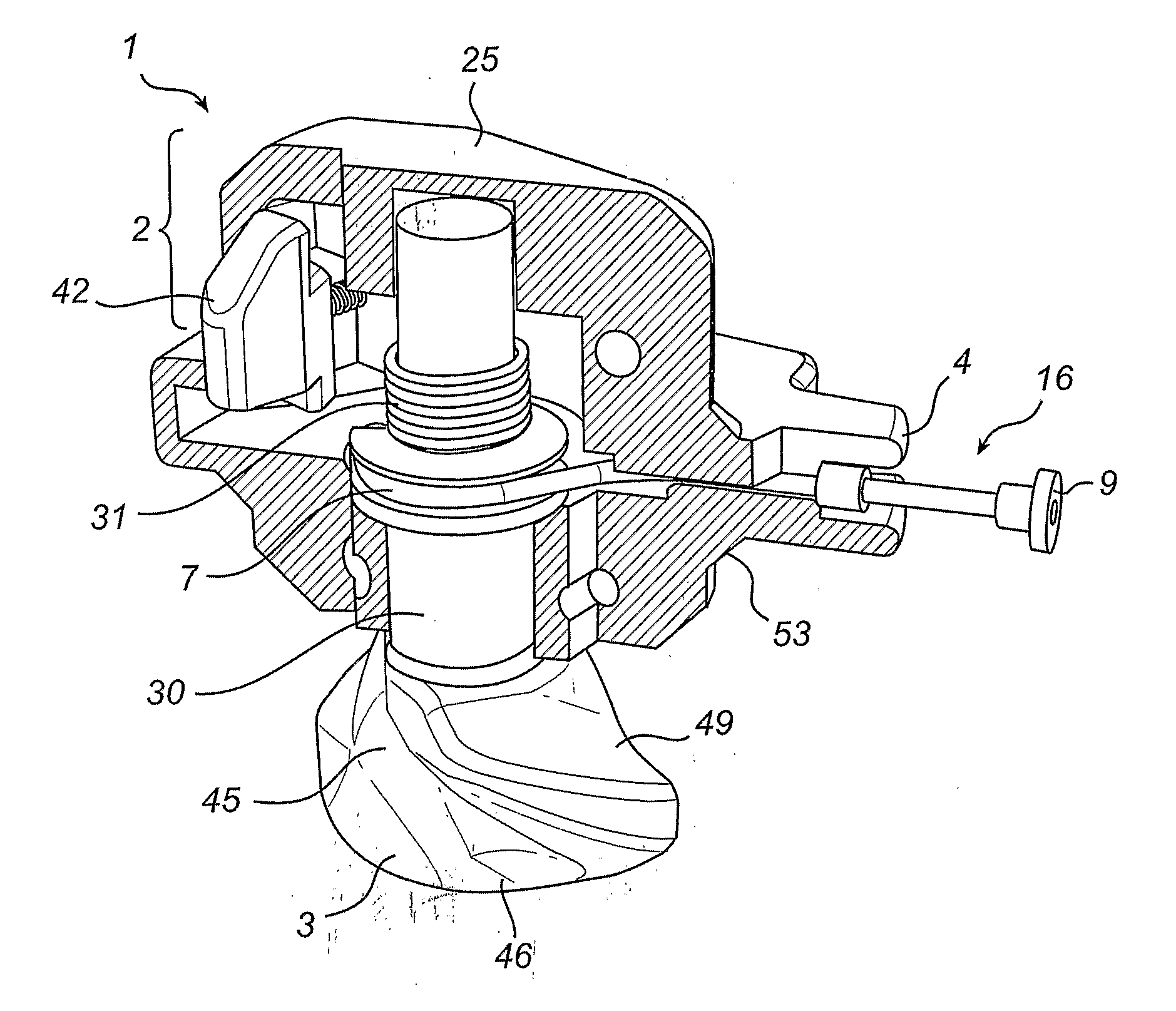
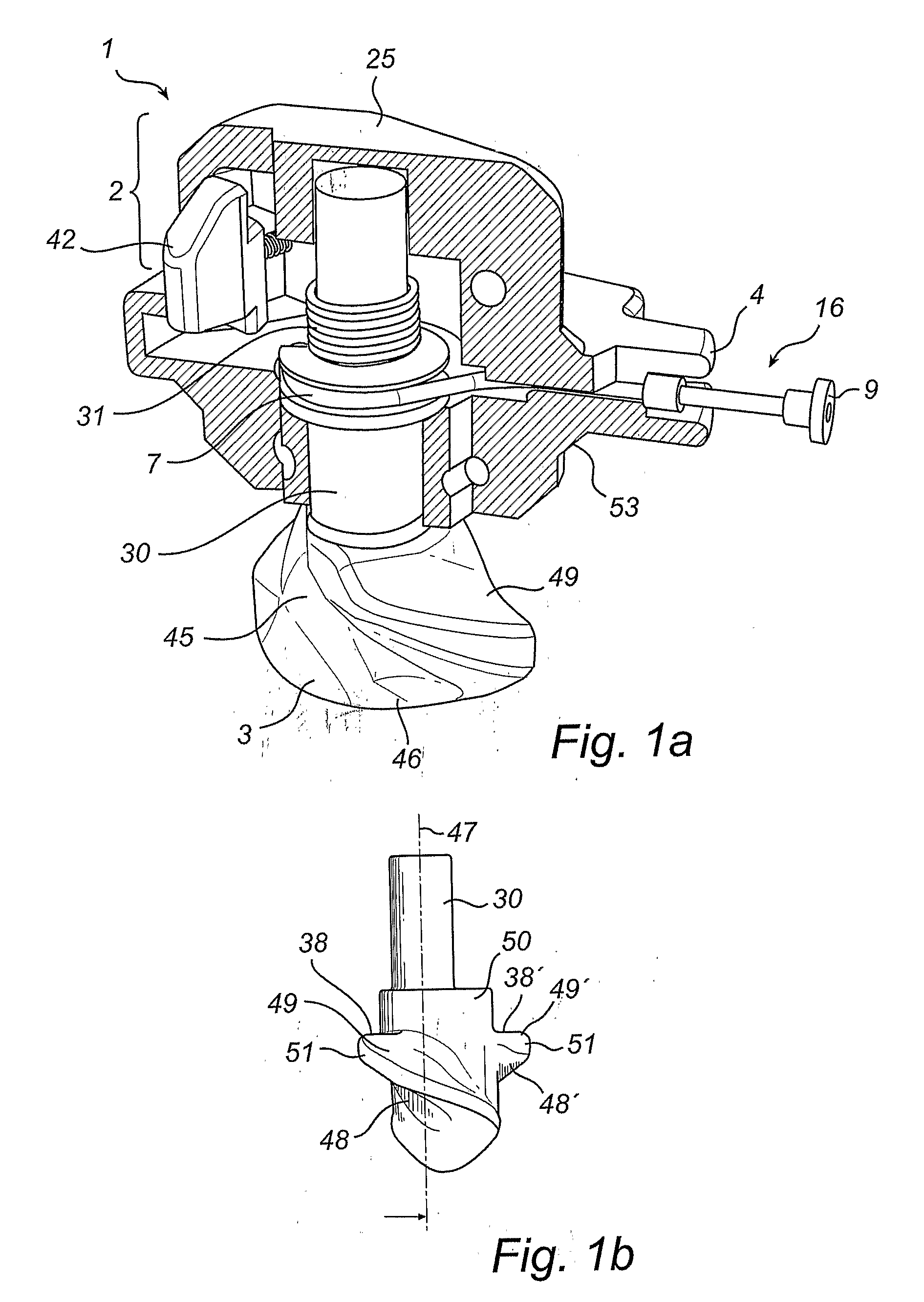
[0080]According to the present invention, shown in FIGS. 1, 3a and 3b, a coupling device 1 comprising a maneuvering means 16 arranged in relation to the second engaging portion 3 may achieve this temporary elimination of the fully automatic feature. As may be seen in FIGS. 1, 3a and 3b, the maneuvering means 16 according to this embodiment comprises a wire 7 and an end knob 9. The wire 7 is attached to the axle 30, which in turn is attached to the second engaging portion 3. As may also be seen in FIGS. 3a and 3b, the section 4 of the housing 25 comprises two interconnected openings 36 and 37, through which the wire 7 may extend and the end knob 9 is positioned outside the housing 25. Due to the interconnection between the two openings 36,37, the maneuvering means 16 may be brought between two different conditions. When the wire extends through the first opening 36, as in FIG. 3a, the coupling device 1 is in its fully automatic condition. The maneuvering means may alternatively be de...

second embodiment

[0084]the present invention is shown in FIGS. 4a to 4b. In this embodiment, the coupling device 1 further comprises a washer 5 arranged in the housing 25. The washer 5 is rotatably arranged in relation to an upper portion 8 of the axle 30. The washer 5 comprises a locking tooth or engagement means 22, and a corresponding locking device 6 is provided in the housing 25.

[0085]The locking device 6, which in this embodiment comprises a lock lug 23, is fixedly arranged in relation to the housing 25 of the coupling device 1. In this embodiment, the lock lug 23 is made as an integral part of the housing 25. The lock lug 23 is positioned in the same central plane as the locking tooth 22 of the washer 5, wherein said central plane extends in a direction perpendicular in relation to the longitudinal axis of the axle portion 8. The arrangement is such that the locking tooth 22 of the washer 5 may be brought into engagement with the lock lug 23 of the locking device 6.

[0086]The upper portion 8 o...

third embodiment

[0094]In FIGS. 5a to 5d the present invention is described. In this embodiment the housing 25 is provided with orientation means, which in this embodiment consists of a projecting nose 34. The projecting nose 34 is connected to, and in this embodiment formed in one piece, with a movable unit 24. The movable unit 24 is movable in a substantially linear path inside the housing 25. Further, the axle 30 is provided with an abutment portion 11 which is arranged above the second engaging portion 3 of the coupling device. The movable unit 24 comprises a recess 32 which allows the abutment portion 11 of the axle 30 to pass the movable unit 24 when the axle 30 rotates due to insertion or removal of the second engaging portion 3 from a corner fitting.

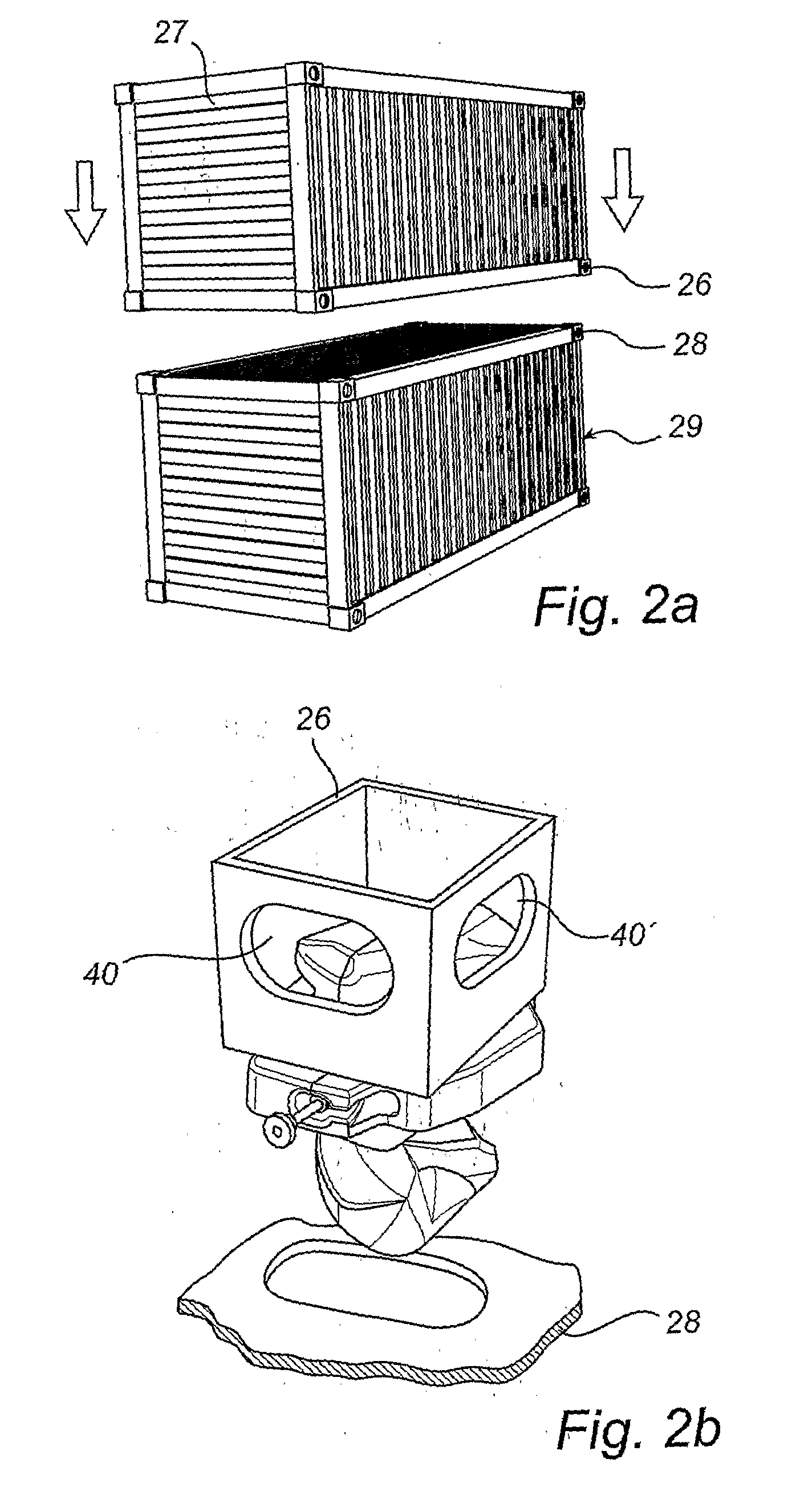
[0095]Corner fittings of an ordinary ISO container usually only have two side openings 40,40′, positioned at adjacent walls, thereby positioning the side openings 40,40′ perpendicularly in relation to each other. Due to the design of the housing ...


PUM


Abstract

A coupling device and method for enabling simultaneous lifting of two containers (27,29) interconnected with a coupling device (1), wherein said coupling device (1) comprises two engaging portions (2,3) each adapted to be at least partially inserted into a corner fitting of a respective container. The coupling device (1) is provided with an automatic condition, in which automatic condition said engaging portions (2,3) are adapted to engage said corner fitting (26,28) for holding said coupling device (1) in said corner fitting (26,28) and wherein said coupling device (1) further is adapted to upon a prescribed relative movement between said containers (26,28) allow removing of at least one of said engaging portions (2,3) from its respective corner fitting. The method comprises; interconnecting said containers (27,29) by means of said coupling device, and activating a means adapted for alternating said coupling device (1) between said automatic condition and a locked condition, in which locked condition said containers will remain interconnected.

Description

TECHNICAL FIELD OF THE INVENTION[0001]The present invention relates to a method for enabling simultaneous lifting of two containers interconnected with a coupling device, wherein said coupling device comprises two engaging portions adapted to each be at least partially inserted into a corner fitting of a respective container, wherein said coupling device is provided with an automatic condition, in which automatic condition said engaging portions are adapted to engage said corner fitting for holding said coupling device in said corner fitting and wherein said coupling device further is adapted to upon a prescribed relative movement between said containers allow removing of at least one of said engaging portions from its respective corner fitting.[0002]The present invention also relates to a coupling device to be used in such a method.BACKGROUND ART[0003]When transporting goods, for instance, on cargo ships, trains and trucks, part-load, freight and thermo-containers are used to a gre...

Claims


Application Information

Patent Timeline
IPC IPC(8): B65D90/00
CPCB60P7/132Y10T24/28B65D90/0013B63B25/004
Inventor BOMAN, HANSKARLSSON, TORBJORN
Owner CARGOTEC FINLAND
Learn More