
Template creation method and image processor therefor

a technology of image processing and template creation, applied in the field of template creation method and image processing therefor, can solve the problems of inability to improve the success rate of image recognition and its performance beyond a certain level, and achieve the effect of improving image recognition performan

Active Publication Date: 2009-12-10
HITACHI HIGH-TECH CORP
View PDF18 Cites 4 Cited by
  • Summary
  • Abstract
  • Description
  • Claims
  • Application Information

AI Technical Summary

Benefits of technology

The present invention provides a method, apparatus, and program for creating a template for image recognition based on design data. The template is created by setting luminance information for each area in the template based on the material information of the region defined by the template. This luminance information can include information from pattern size, setup conditions, layer information, and outline information. By using this template for image recognition, the matching rate between the template and the actual image can be increased, resulting in improved image recognition performance. The invention also allows for easy creation of a template based on design data without acquiring an actual image.

Problems solved by technology

In image recognition with the use of design data, however, the pattern edge information can be utilized, but the contrast information cannot.
Thus, a problem with the latter image recognition is that the success rate of image recognition and its performance cannot be improved beyond a certain level, in comparison with the former image recognition involving comparison between the two images of the same type (e.g., between SEM images or between OM images).
However, Patent Document 1 is not designed to use the contrast information, which is not present in design data, so as to increase its image recognition performance up to the level of the image recognition that involves same-type image comparison.

Method used


Image

  • Template creation method and image processor therefor
  • Template creation method and image processor therefor
  • Template creation method and image processor therefor

Examples


Embodiment Construction

[0021]Described hereinafter with reference to the accompanying drawings is a template creation method with the use of design data, an embodiment of the invention.

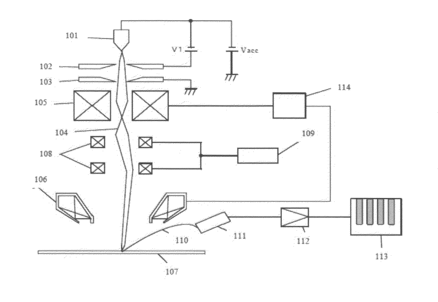
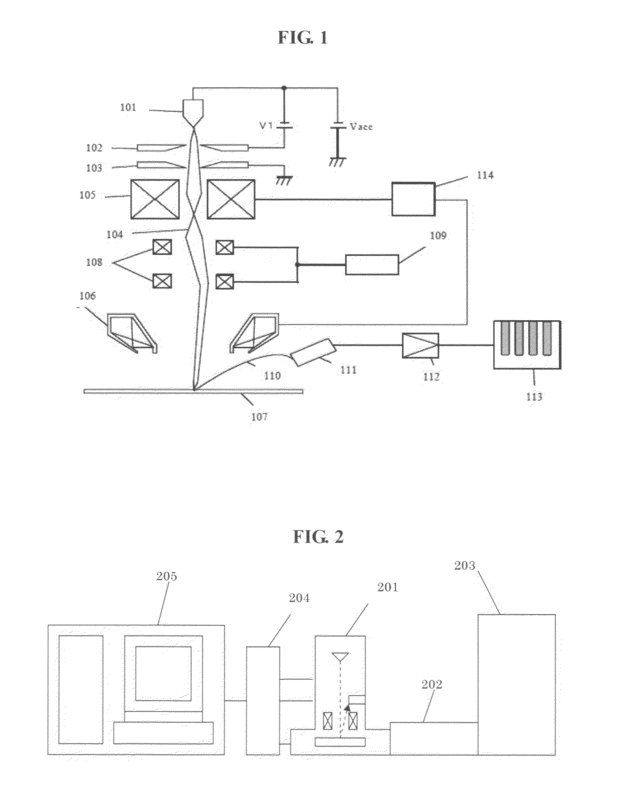
[0022]FIG. 1 shows one of the exemplary configurations of an SEM. In the SEM, a primary electron beam 104 is applied to a cathode 101 and a first anode 102 and accelerated toward the subsequent-stage lens system by a voltage Vacc (acceleration voltage) applied to a second anode 103.

[0023]The primary electron beam 104 is focused as a tiny spot onto a sample (synonymous with “wafer” or “semiconductor device”) 107 by a convergent lens 105 and an objective lens 106, both controlled by a lens control power supply 114. The focused primary electron beam 104 is then two-dimensionally scanned across the sample 107 by two-stage deflecting coils 108. Scanning signals for the deflecting coils 108 are controlled by a deflection control device 109 based on desired image magnifications. By the primary electron beam 104 being scanned acros...


PUM


Abstract

An object of the present invention is to maintain the ease with which a template is created based on design data without acquiring an actual image, which is achieved by providing the template with equivalent information contained by a template used for image recognition that involves same-type image comparison, and to improve image recognition performance by increasing the matching rate between a template and an actual image.To achieve the above object, the present invention provides a method, apparatus, and program for creating based on design data a template that is used for image recognition, wherein luminance information is set for each area in the template based on the material information of the region defined by the template. Specifically, the luminance information is set based on at least one of information from among the above material information, the pattern size information of a pattern arranged in the region defined by the template, the setup conditions of an imaging apparatus, the layer information of the region defined by the template, and the outline information of a pattern.

Description

BACKGROUND OF THE INVENTION[0001]1. Field of the Invention[0002]The present invention relates to a method for creating templates that are used to detect a particular position in a semiconductor device and to an image processor and a program therefore and, in particular, to a template creation method based on the design data of a semiconductor device or the like.[0003]2. Description of the Related Art[0004]Conventional semiconductor measurement devices recognize an image by comparison between SEM (scanning electron microscope) images, between an SEM image and an OM (optical microscope) image, or between OM images. In contrast, some of recent image recognition technologies utilize design data to recognize an image as in comparison between design data and an SEM image or between design data and an OM image.[0005]For example, Japanese Unexamined Patent Application Publication No. 2002-328015 (Patent Document 1, corresponding to U.S. Pat. No. 7,026,615) discloses a technique for creating...

Claims


Application Information

Patent Timeline
Patent Type & Authority Applications(United States)
IPC IPC(8): G06K9/62
CPCG01N2021/95615G01N21/95607
Inventor YANG, KYOUNGMONISHIHARA, MAKOTOKOSHIHARA, SHUNSUKE
Owner HITACHI HIGH-TECH CORP
Learn More