
Power factor correction rectifier that operates efficiently over a range of input voltage conditions

a power factor correction and rectifier technology, applied in the direction of electric variable regulation, process and machine control, instruments, etc., can solve the problems of significant losses, large difference between input and output voltage, and significant low efficiency of the pfc boost rectifier at minim low line input voltage, so as to increase the output voltage

Active Publication Date: 2009-12-10
DELTA ELECTRONICS INC
View PDF15 Cites 60 Cited by
  • Summary
  • Abstract
  • Description
  • Claims
  • Application Information

AI Technical Summary

Benefits of technology

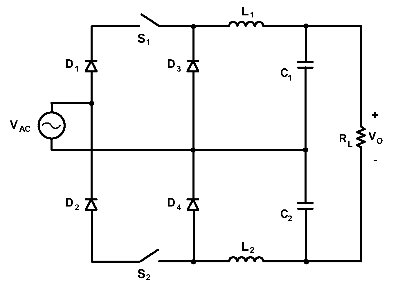
The present invention is about a PFC rectifier that has two converters that increase the output voltage of the rectifier. The converters can be serially coupled together, and they can form a bi-directional ac-ac inverter. The rectifier can have a linear or nonlinear input-to-output voltage gain mode, and it can also have a DC-DC converter. The output capacitors can be coupled to sensors for controlling the switching in the converters. The technical effects of this invention are that it allows for a higher output voltage and more efficient power conversion.

Problems solved by technology

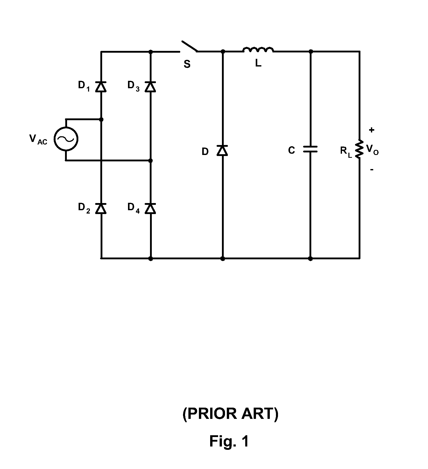
However, a drawback of the PFC boost rectifier is significantly low efficiency at minim low line input voltage, e.g., around 85 volts.
As a result, the difference between input and output voltages is large when the boost rectifier operates at maximum high line voltage.
Consequently, the boost converter needs to store and circulate extra energy to increase the voltage, which results in significant losses and lower efficiency at minimum low line voltage.
In addition, a converter generally has higher conduction losses when it operates at low line since the magnitude of input current is inversely proportional to the input voltage to process the equal power.
As a result, a PFC boost rectifier shows significantly lower efficiency at low line than that at high line input voltages.
As a result, the PFC boost rectifier must be designed to accommodate high thermal dissipations at 92% efficiency, which can increase its cost.
Moreover, the efficiency may not be degraded at high line since its input current is smaller than that at low line input voltage.
Although, the lower output voltage produced by a buck PFC rectifier benefits efficiency, it also provides a disadvantage by reducing energy storage capability, which an off-line power supply needs to maintain its output within the specified time period after a drop-out of the line voltage.
Since the stored energy is proportional to the square of the voltage across the capacitor, the low output voltage of the PFC buck rectifier significantly limits the useable energy during the specified time.
However, the voltage doubler of FIG. 2 is not suitable for applications that require PFC.

Method used


Image

  • Power factor correction rectifier that operates efficiently over a range of input voltage conditions
  • Power factor correction rectifier that operates efficiently over a range of input voltage conditions
  • Power factor correction rectifier that operates efficiently over a range of input voltage conditions

Examples


Embodiment Construction

[0064]A PFC rectifier according to the present invention offers maximized low line efficiencies without the limitations of prior-art techniques are described. According to the present invention, a system and method that substantially improves the efficiency at low line is provided. Moreover, the proposed system and method increases the rectifier output voltage and reduces the number of the input bridge diodes.

[0065]Referring to FIG. 3, the PFC rectifier according to one exemplary embodiment If the present invention comprises a first converter, a second converter, and a voltage multiplier, such as a voltage doubler comprising two serially coupled capacitors. The converters have corresponding first and second switching circuits and inductors. Examples of the first and second converters include buck and buck-boost converters. The first converter couples an input ac source to one capacitor. The second converter couples the input ac source to the other capacitor. In one embodiment, the f...


PUM


Abstract

A PFC rectifier comprises a first converter having a first output capacitor and a second converter having a second output capacitor. The he first and second capacitors are coupled to each other to increase the output voltage of the PFC rectifier. Fore example the first or second output capacitors can be serially coupled to each other. At least one or both of the first or second converters comprise buck or buck-boost converters, including inverting or non-inverter buck converters. The first and second converters can also form a bi-directional ac-ac inverter.

Description

CROSS-REFERENCE TO RELATED APPLICATIONS [0001]This Non-provisional Application claims the benefit of U.S. Provisional Application Ser. No. 61 / 059,087, filed Jun. 5, 2008, titled “A Power Factor Correction Rectifier that Operates Efficiently Over A Range of Input Voltage Conditions”, which is incorporated by reference herein in its entirety.FIELD OF THE INVENTION [0002]This invention relates to the power factor correction (PFC) front-end rectifier, and more particularly to a PFC rectifier with improved efficiency over a wide input voltage range, including improved efficiency from a minimum low line input voltage to a maximum high line input voltage.DESCRIPTION OF THE PRIOR ART [0003]In the field of power supplies, low line voltage refers to a nominal input AC voltage of 110 volts for power supplies operating in one part of the world, e.g., the US, and high line voltage refers to a nominal input voltage of 220 volts for power supplies operating in other parts of the world, e.g., Europ...

Claims


Application Information

Patent Timeline
Patent Type & Authority Applications(United States)
IPC IPC(8): H02M7/00
CPCY02B70/126H02M1/4208Y02B70/10Y02P80/10
Inventor JANG, YUNGTAEKJOVANOVIC, MILAN M.
Owner DELTA ELECTRONICS INC
Learn More